Connecting the Cables
Connecting the power
Currently the PCB is only used by ourselves. Instructions can therefore be found in the same (Dutch) instruction manual.
Connecting the peripherals
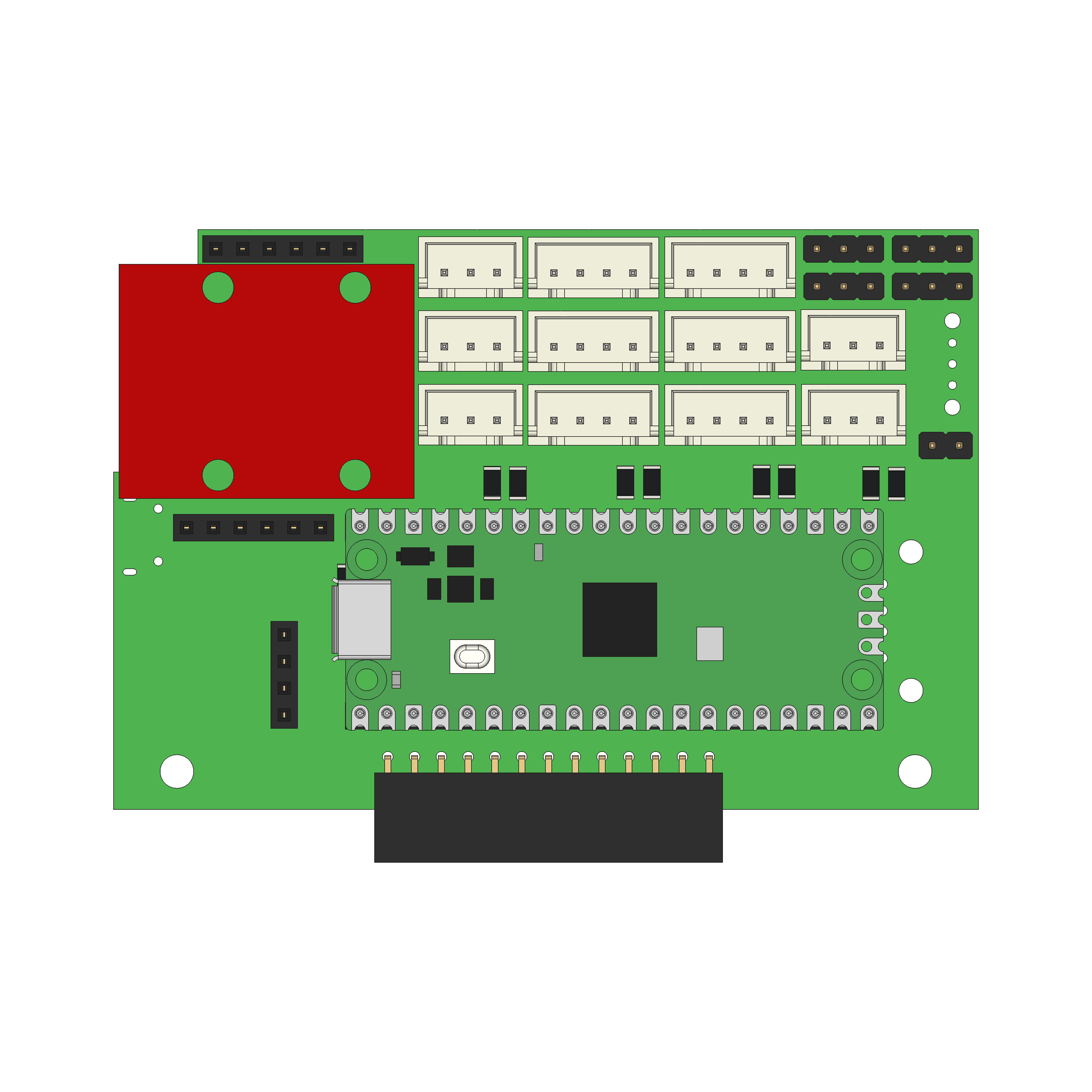
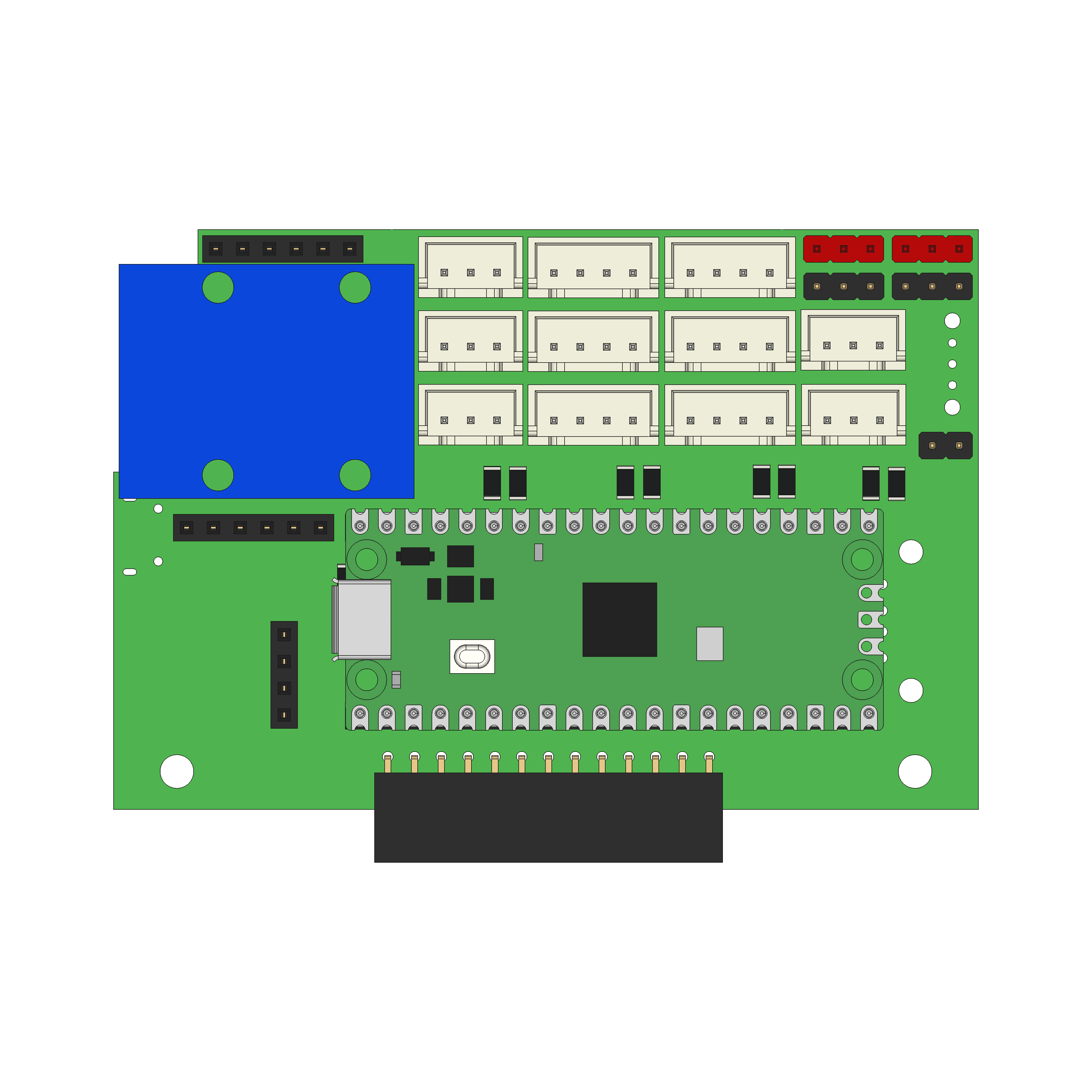
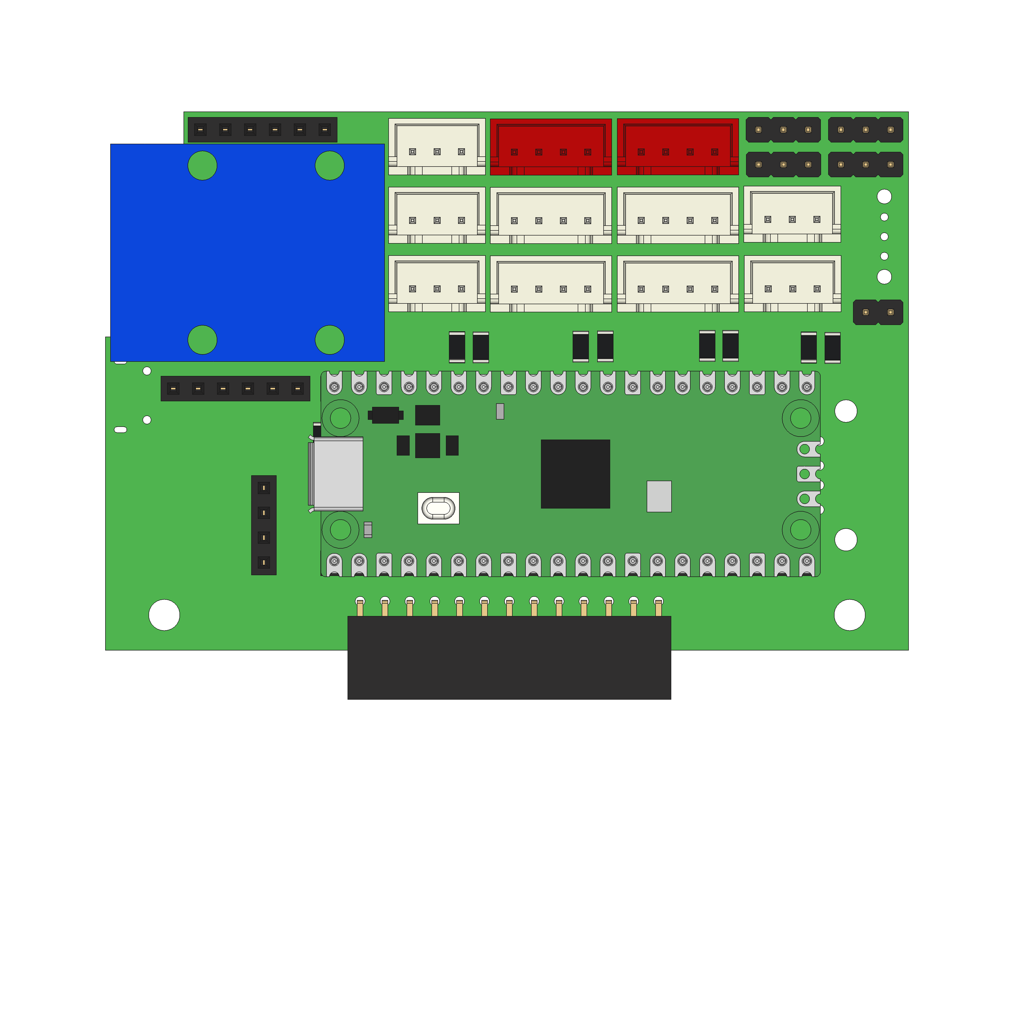
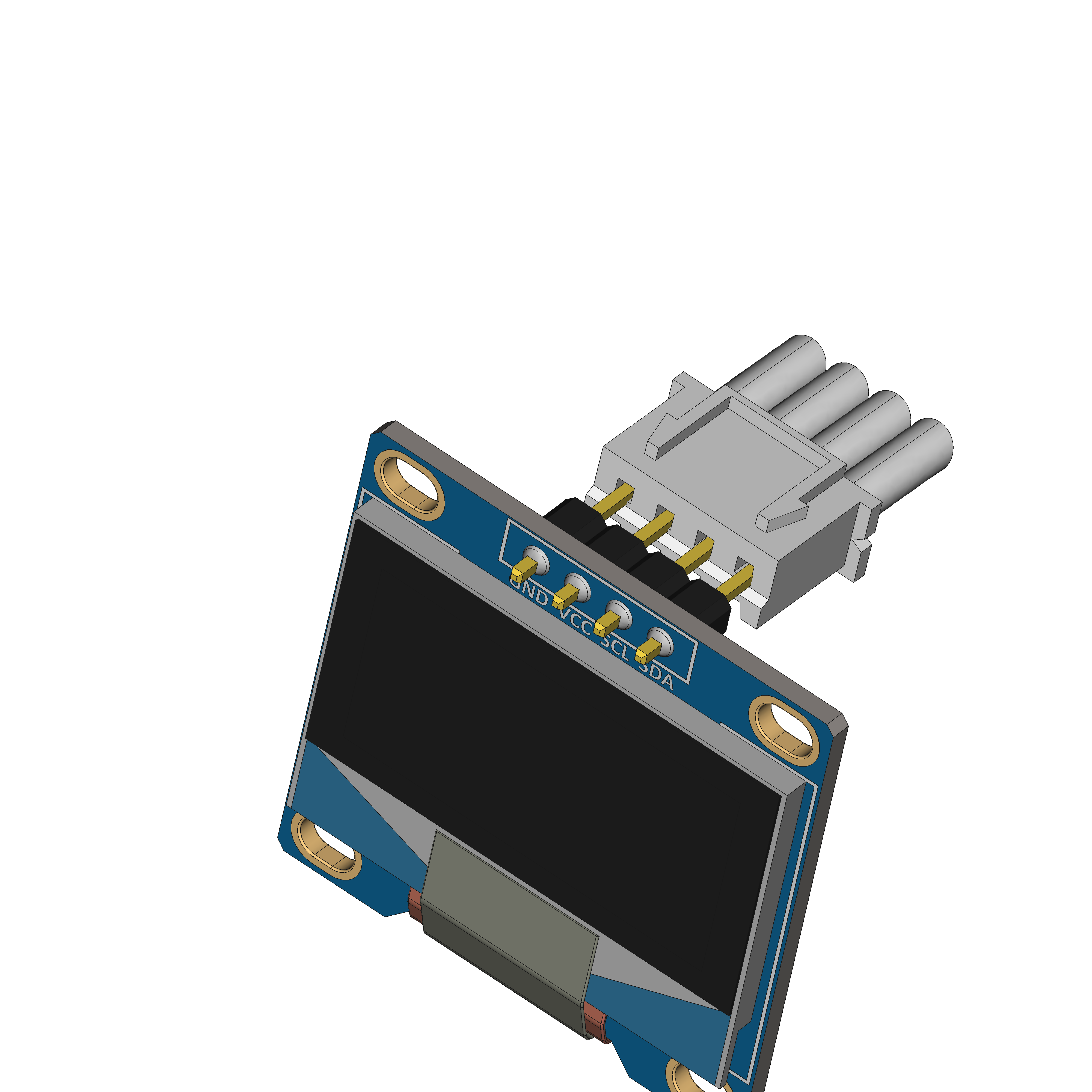
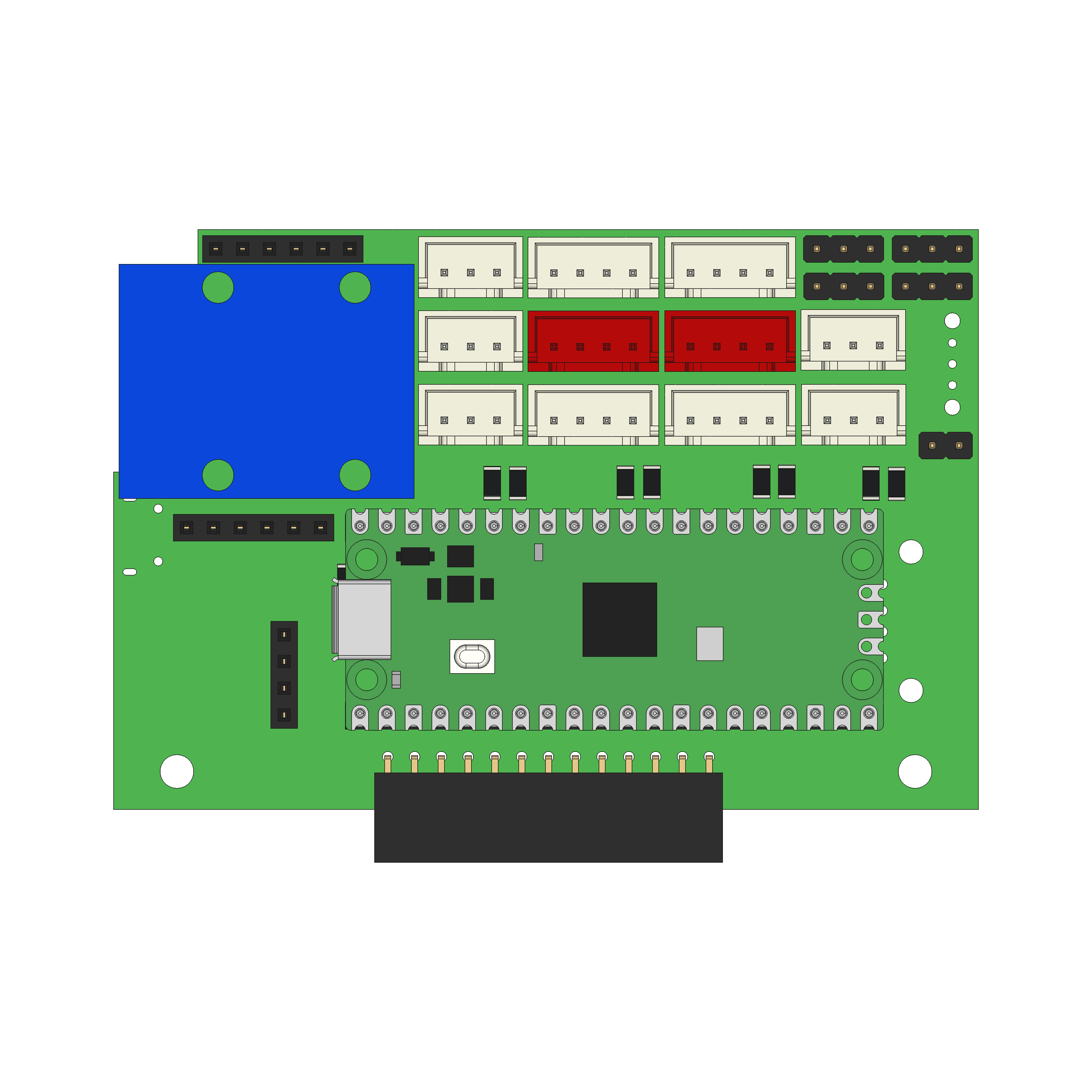
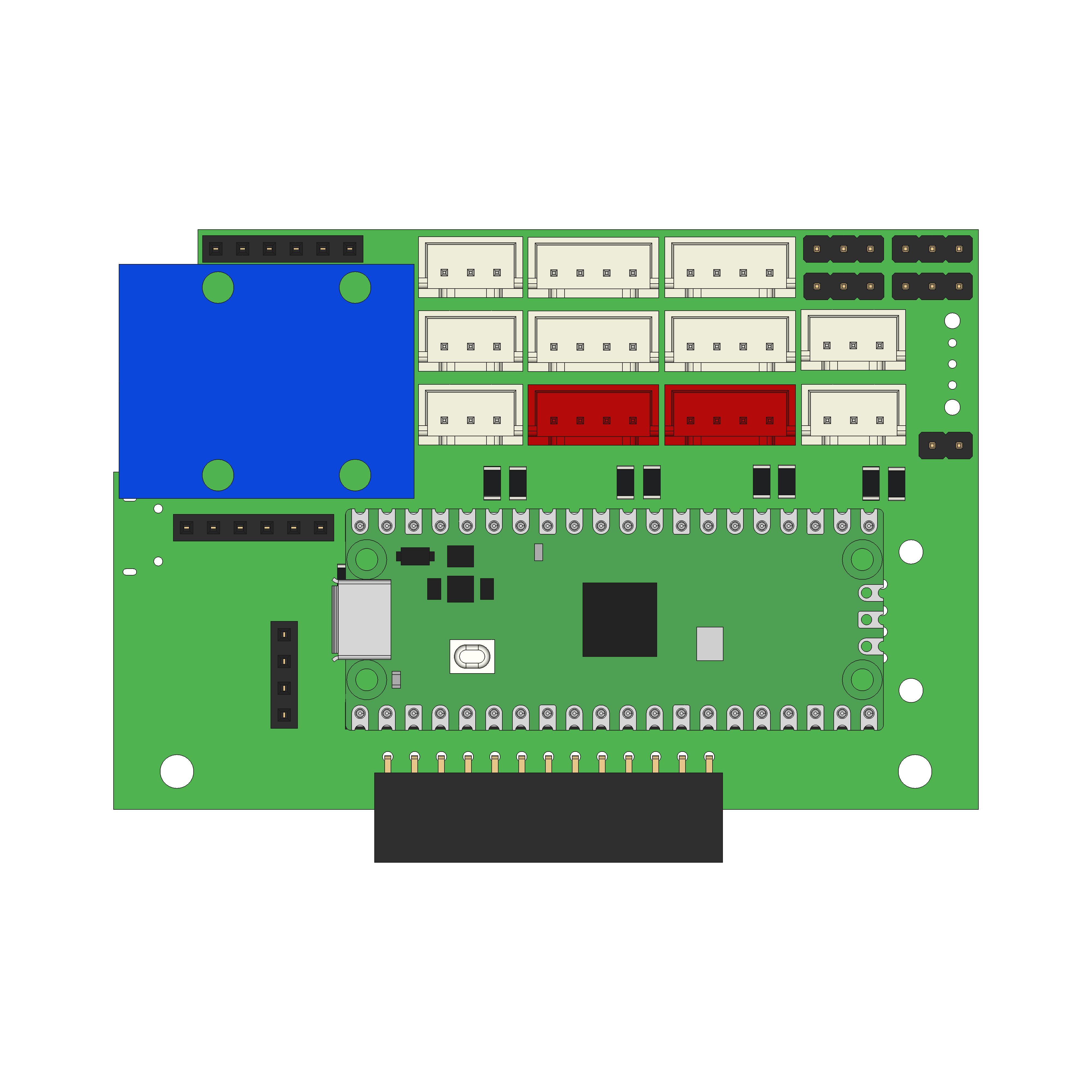
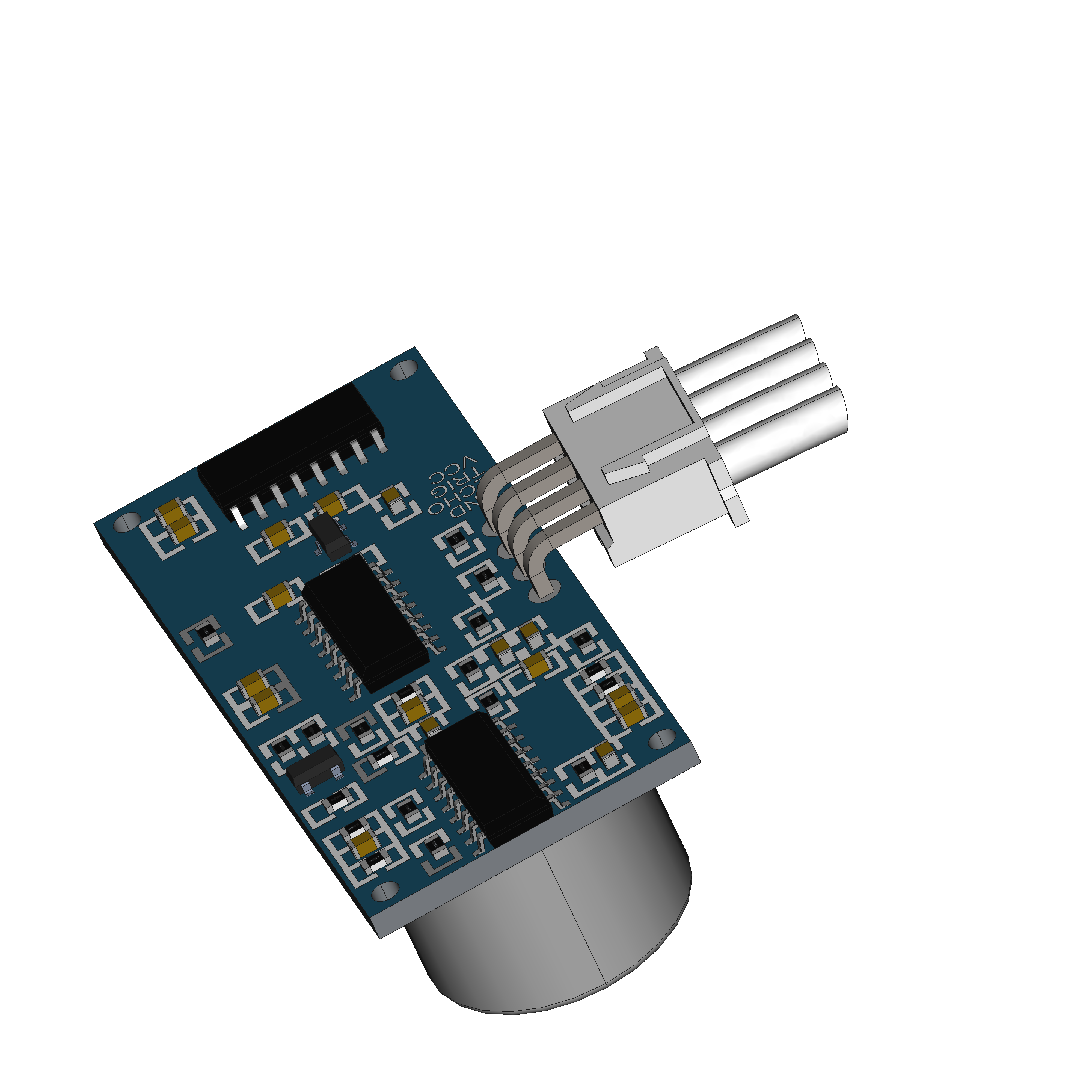
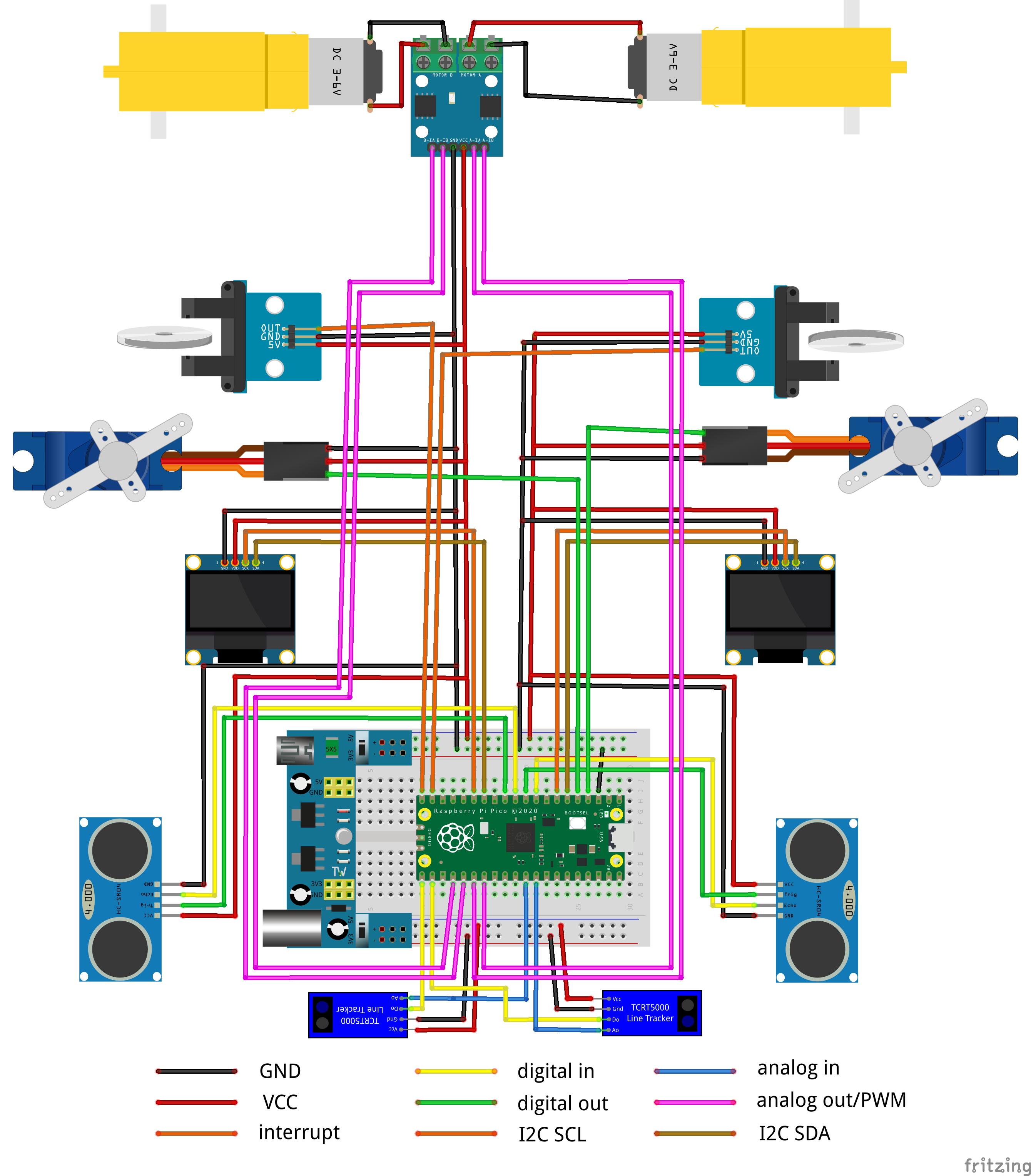
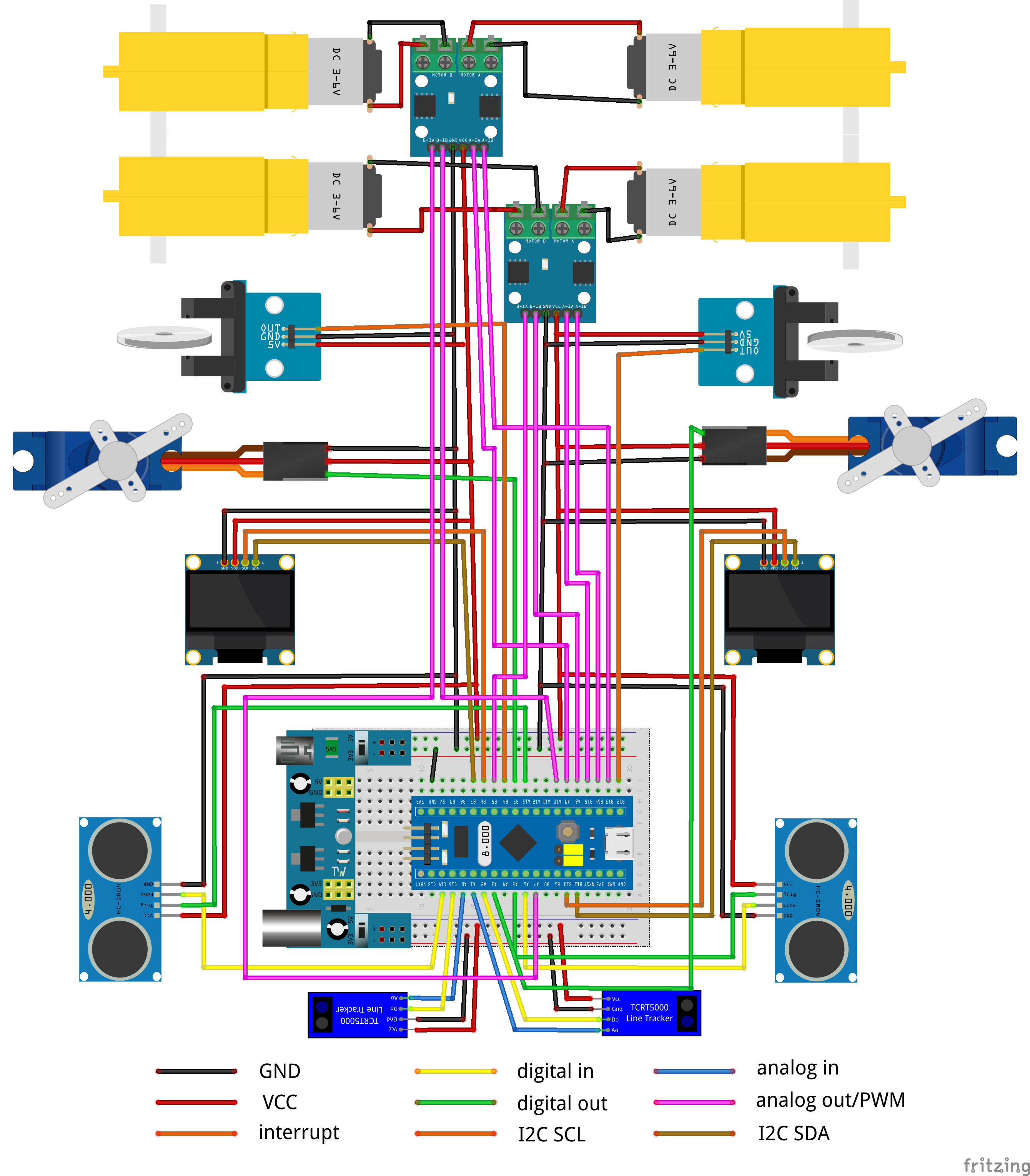
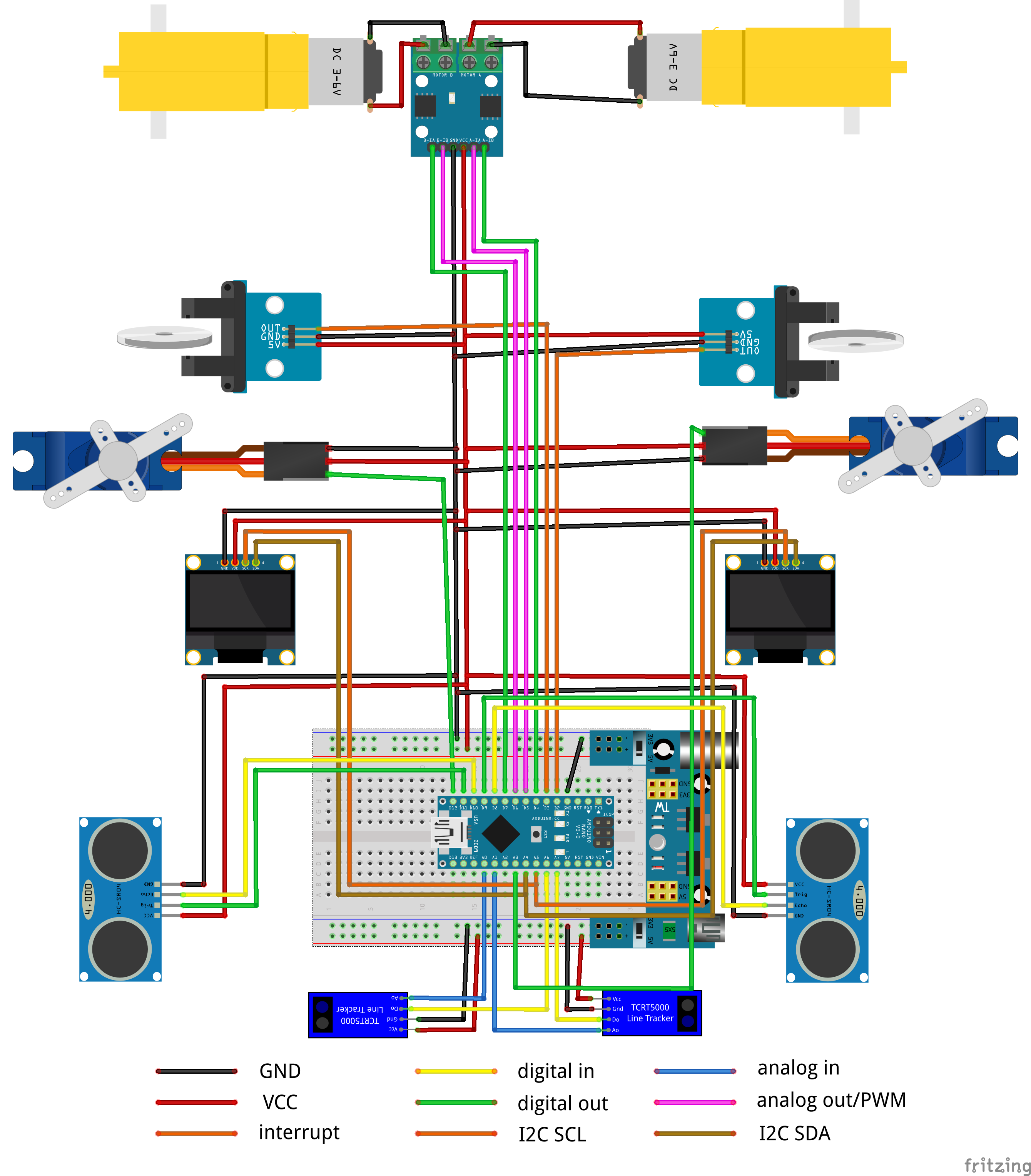
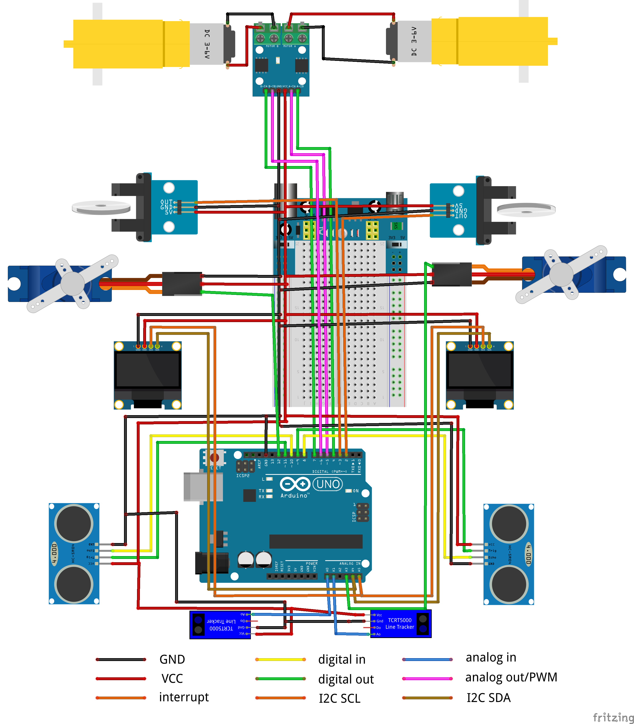
The Mirte PCB is nothing more than just a bunch of cables on a board. You can of course also connect the same hardware to a breadboard. The fritzing image below shows you how to connect all the hardware in order to get the same pin layout as the PCB. But you are also free to chose different pins and change the configuration later on.
Note
Please note that:
The motors are now controlled with one PWM and one digital pin.
Two I2C OLED screens are only possible when you have two OLEDS with different addresses (either by default, or soldered).
Note
Please note that:
The motors are now controlled with one PWM and one digital pin.
Two I2C OLED screens are only possible when you have two OLEDS with different addresses (either by default, or soldered).
The digital value of the IR line sensor is not used.
The power of all peripherals (or at least the motor controller) needs to come from the breadboard power supply.
