Build instructions
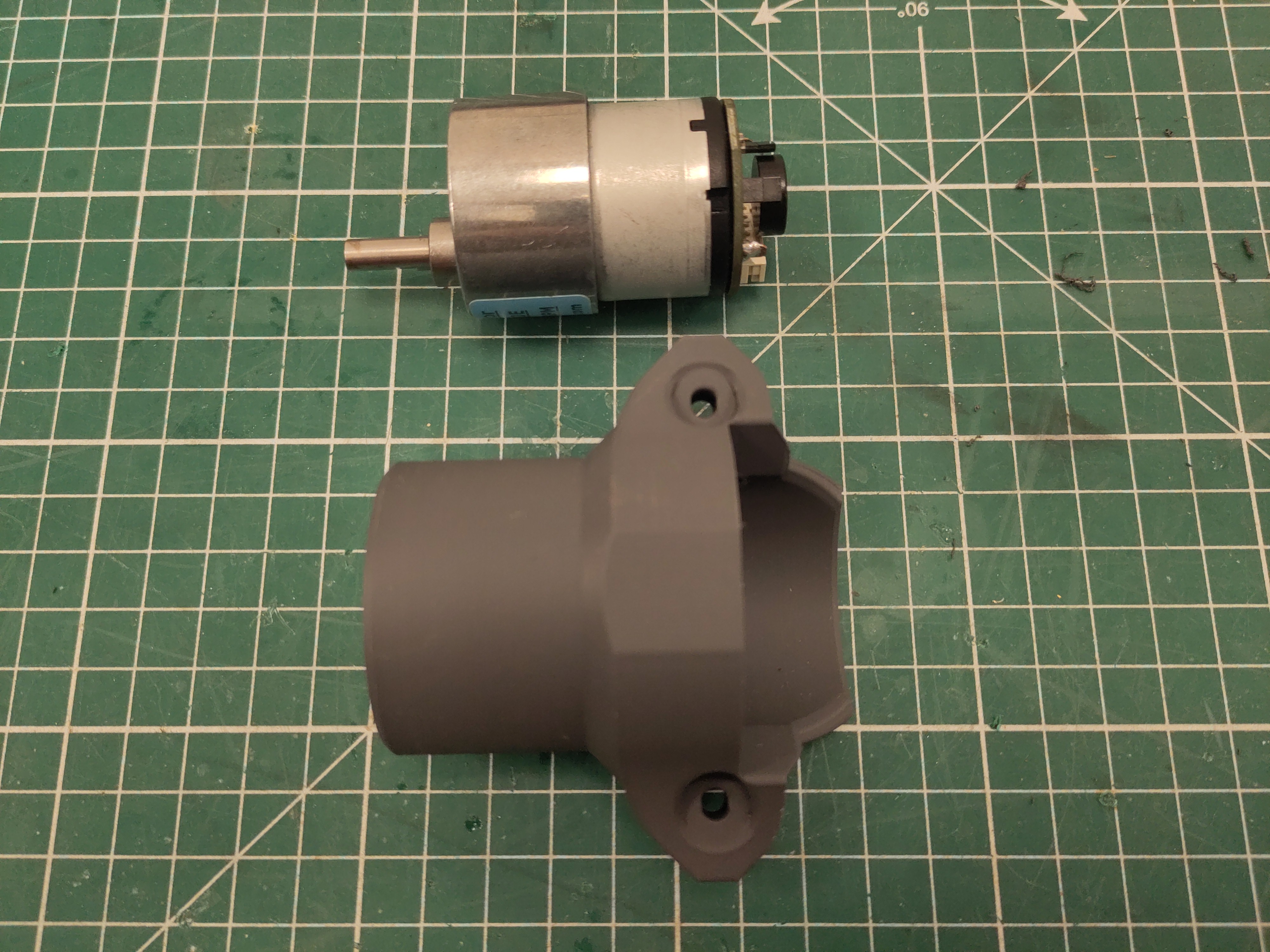
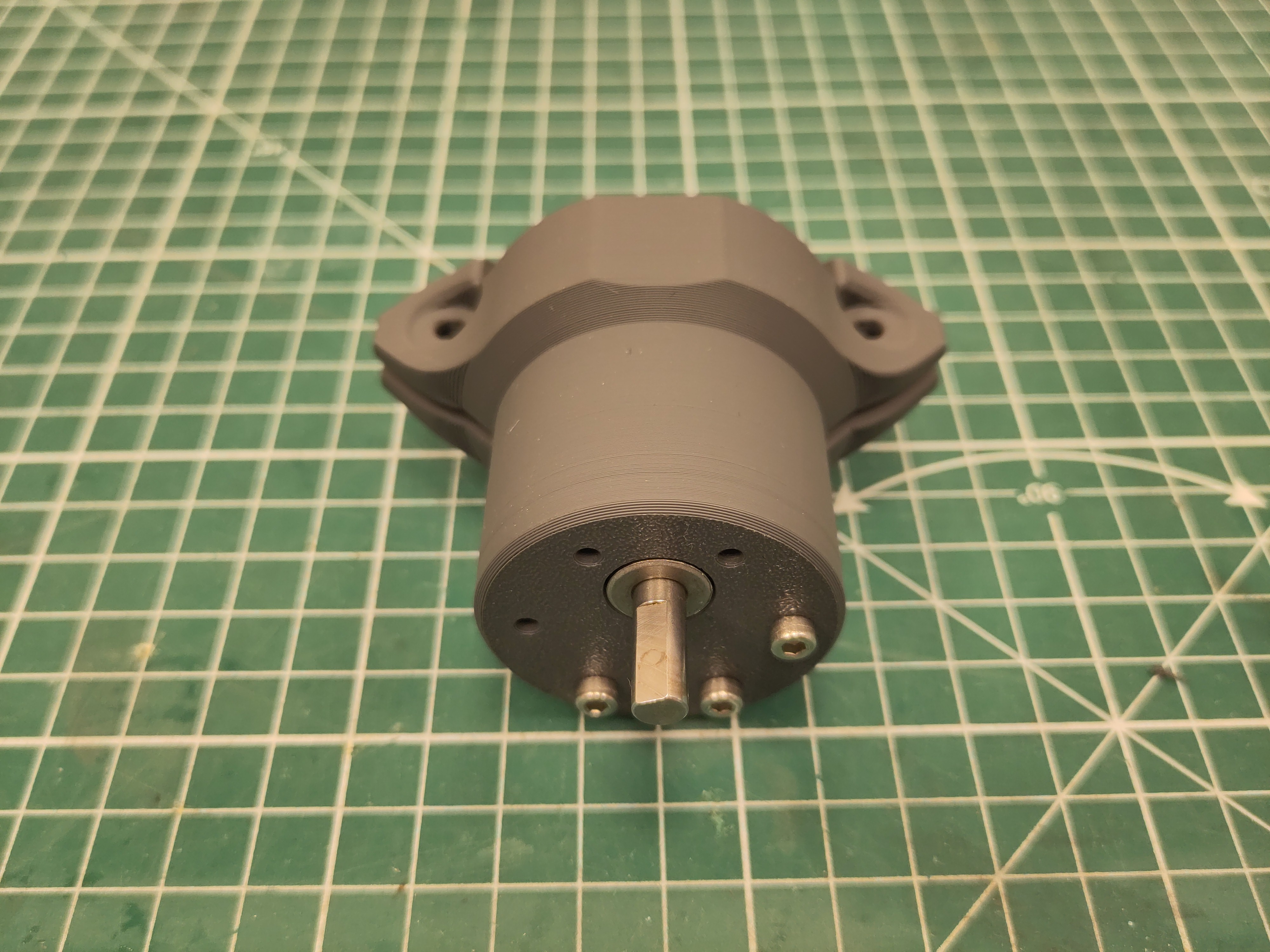
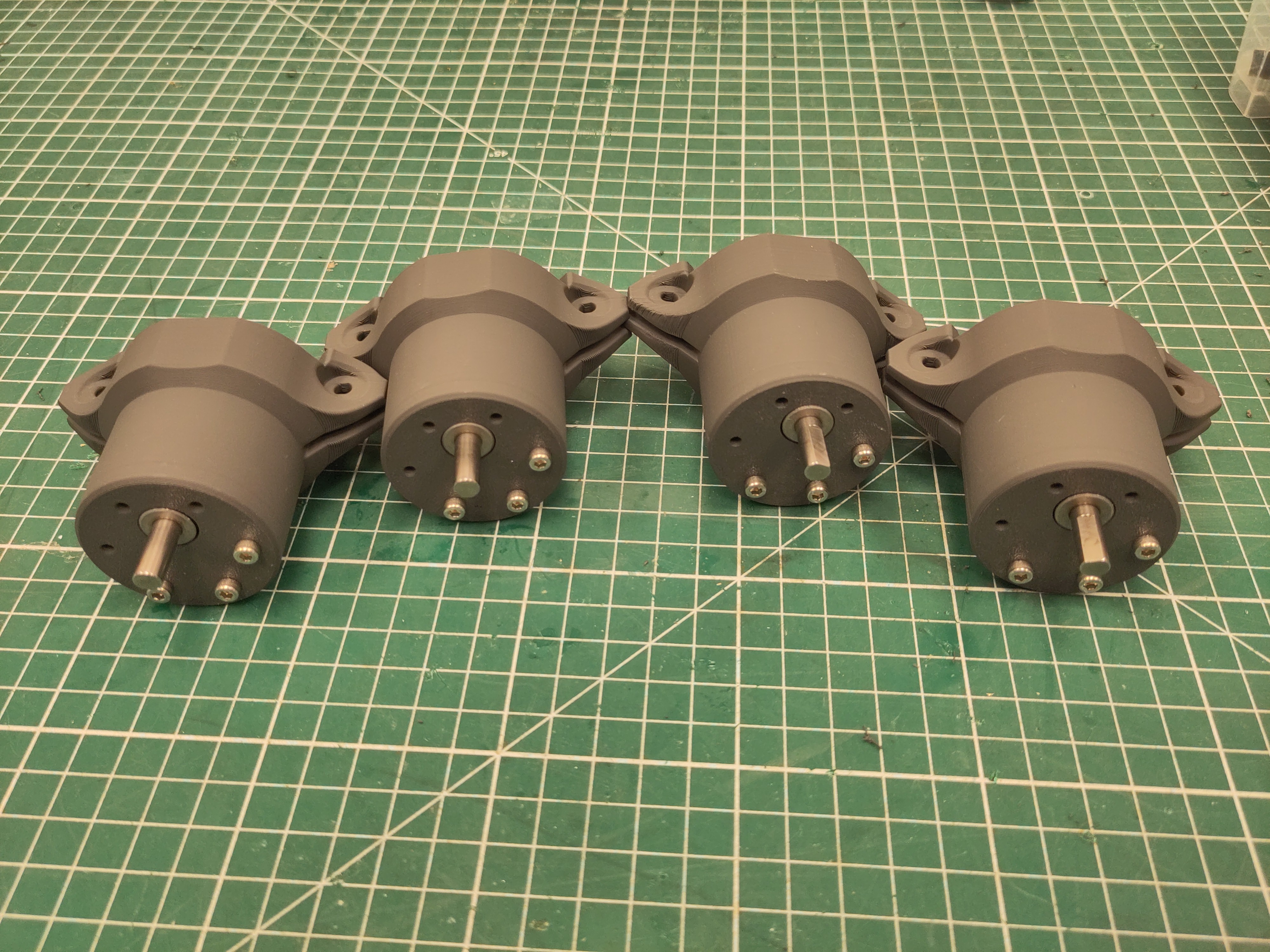
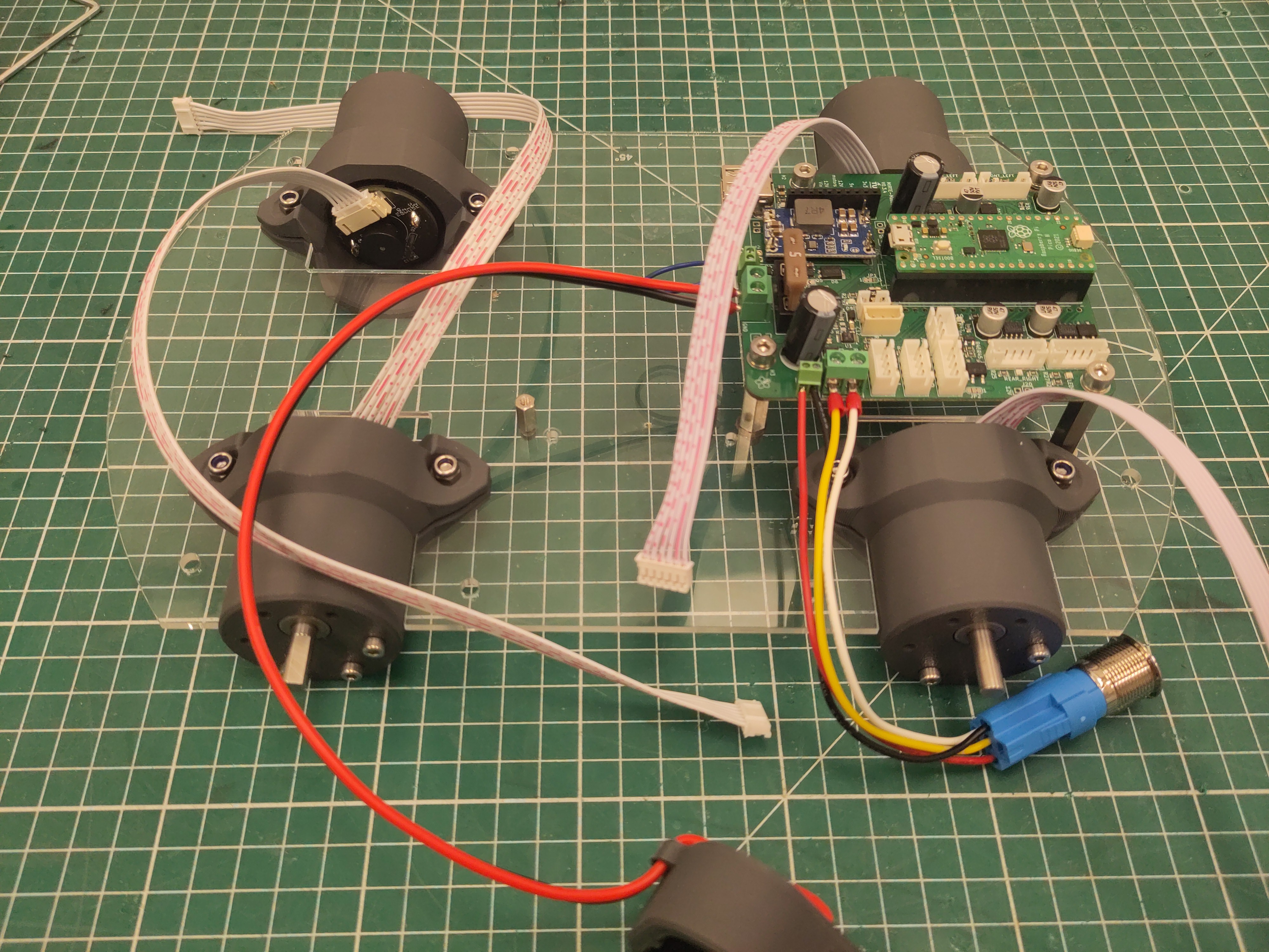
Use the M3 x 12 screw to fix the motor. Make sure to use the three holes as shown otherwise the screw will block the gearbox.
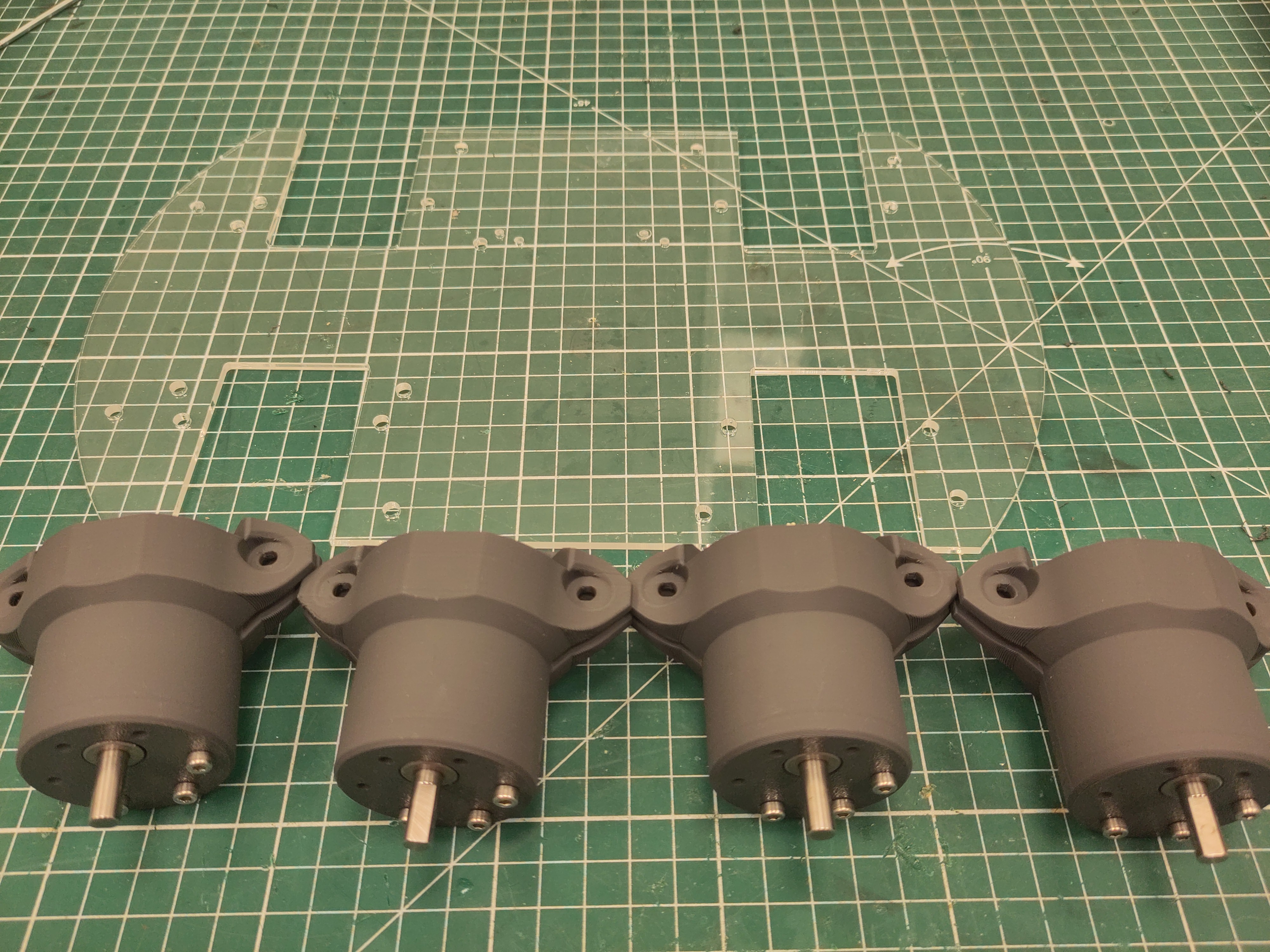
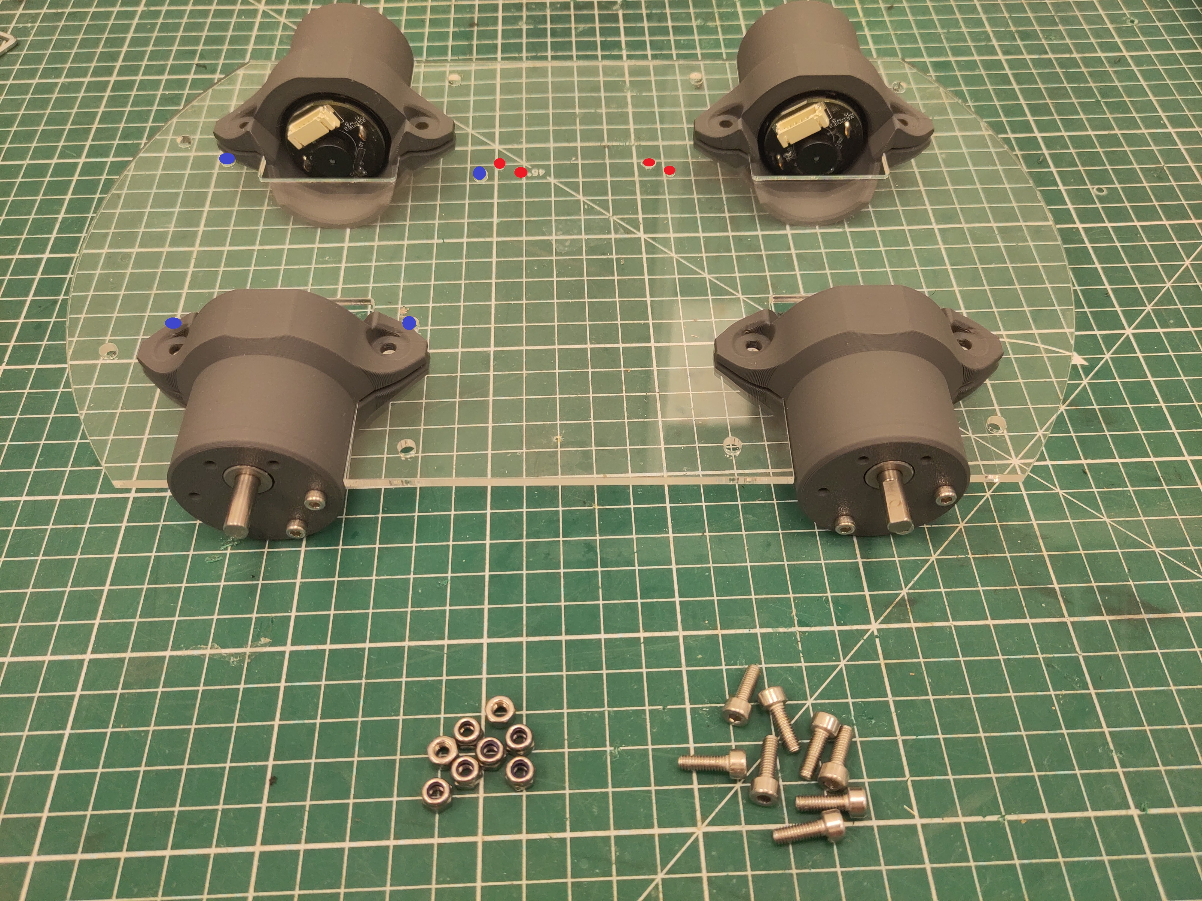
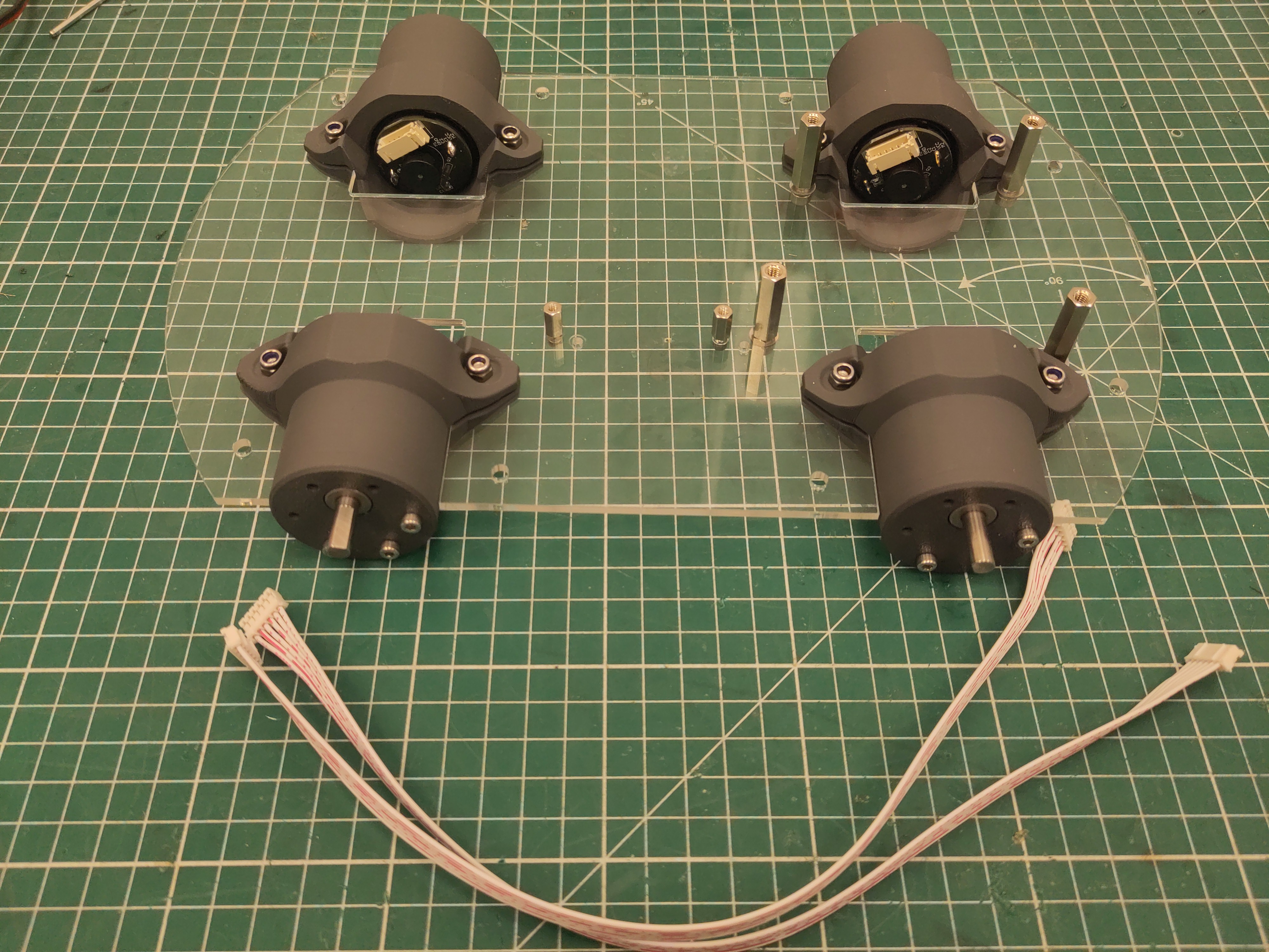
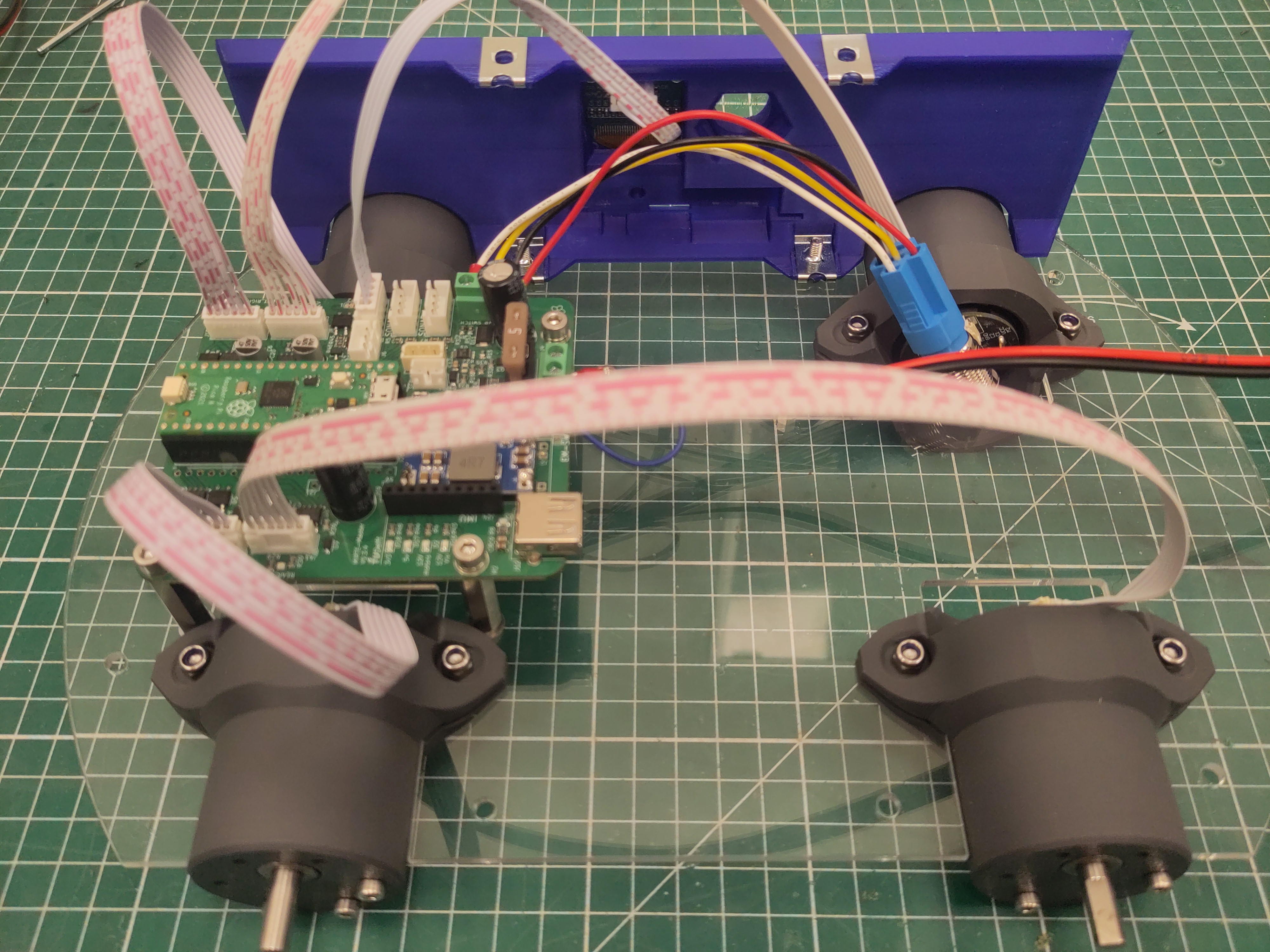
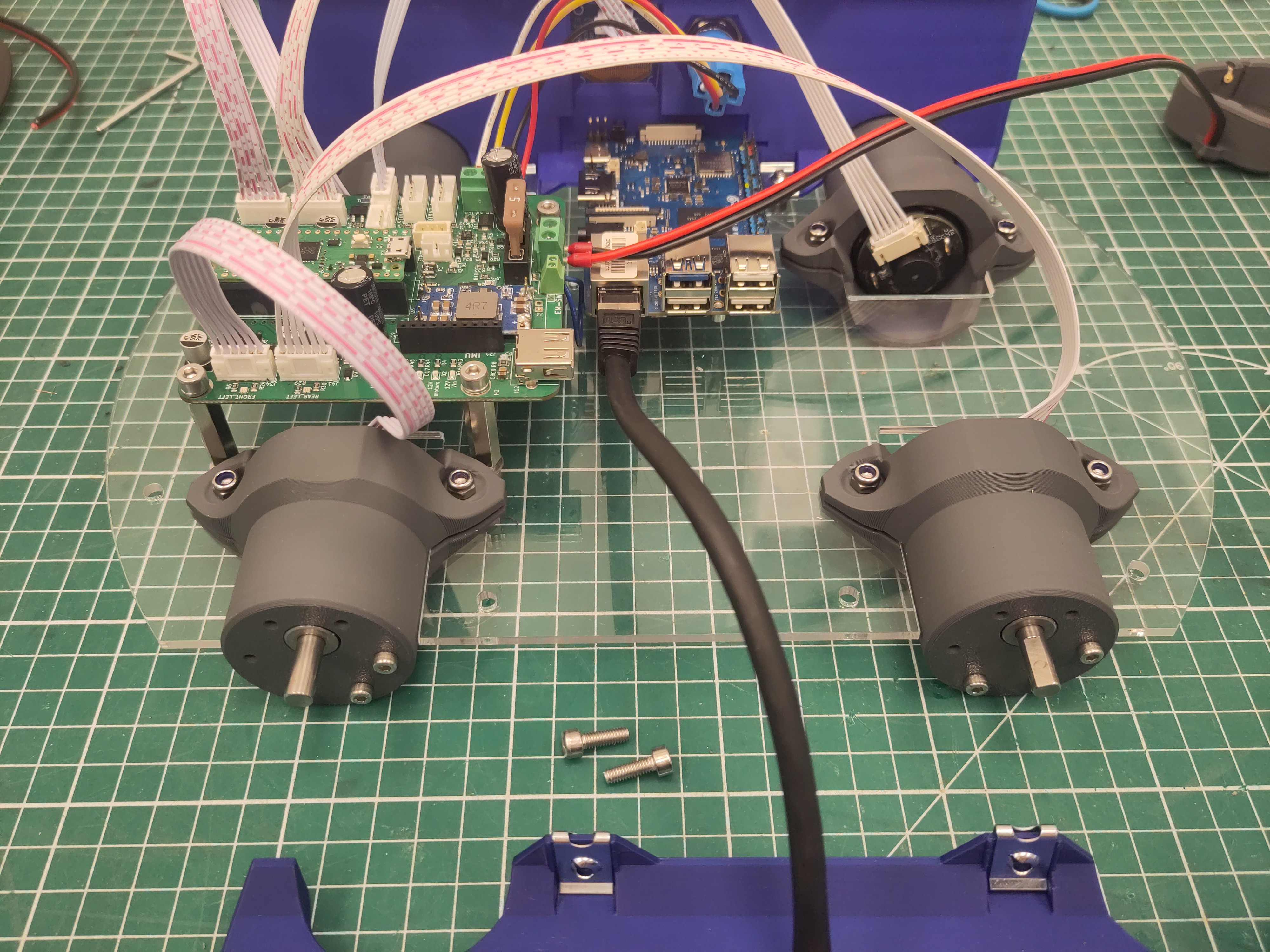
Slide the motors in place. Make sure the orientation of the plate is correct, by looking at the holes of the PCB (blue) and OrangePi (red). Use the M4 x 16 screws and M4 locknut to tighten the motors.
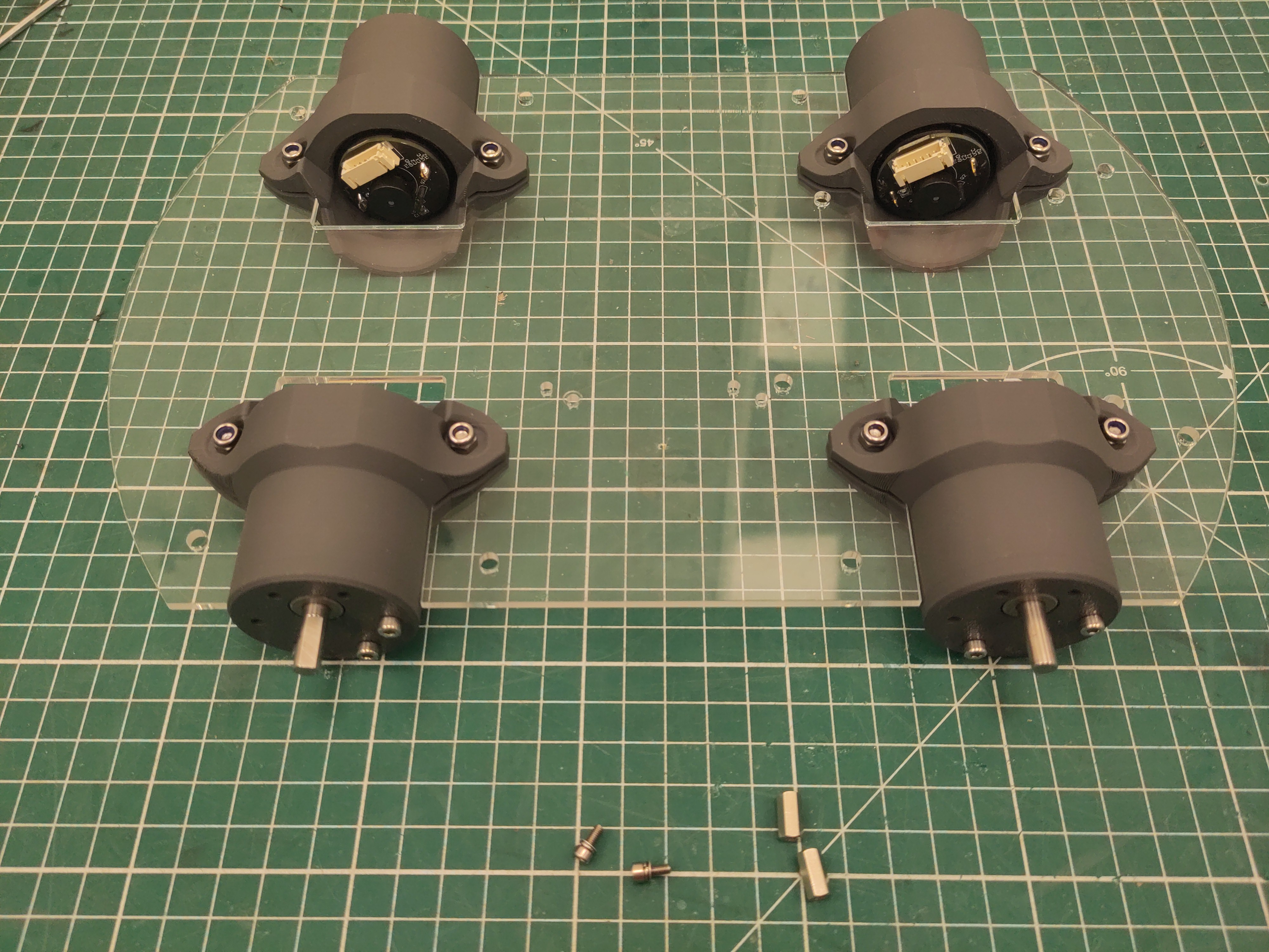
Use the M2.5 standoff and M2.5 x 6 screws (with washer and spring washer).
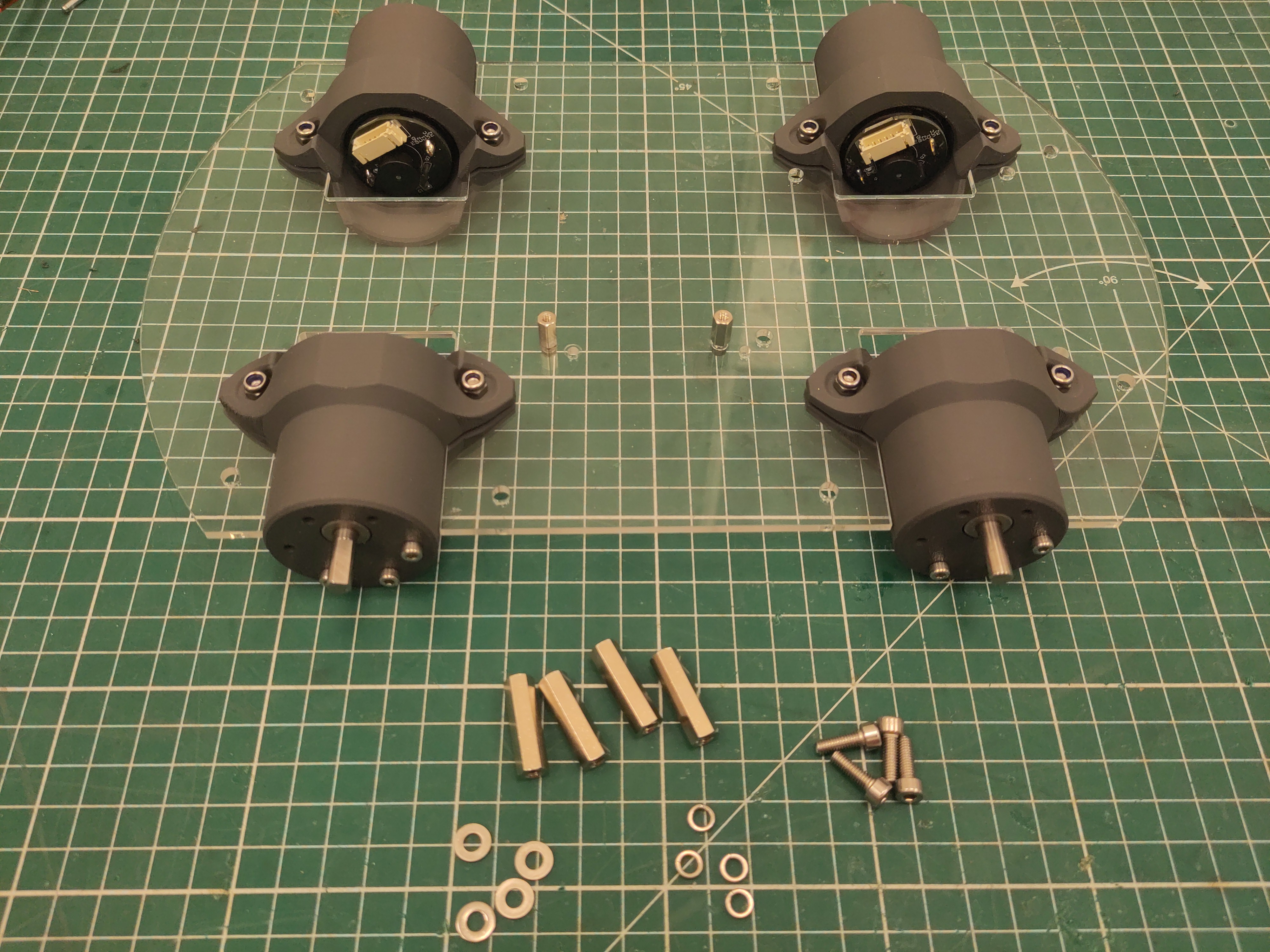
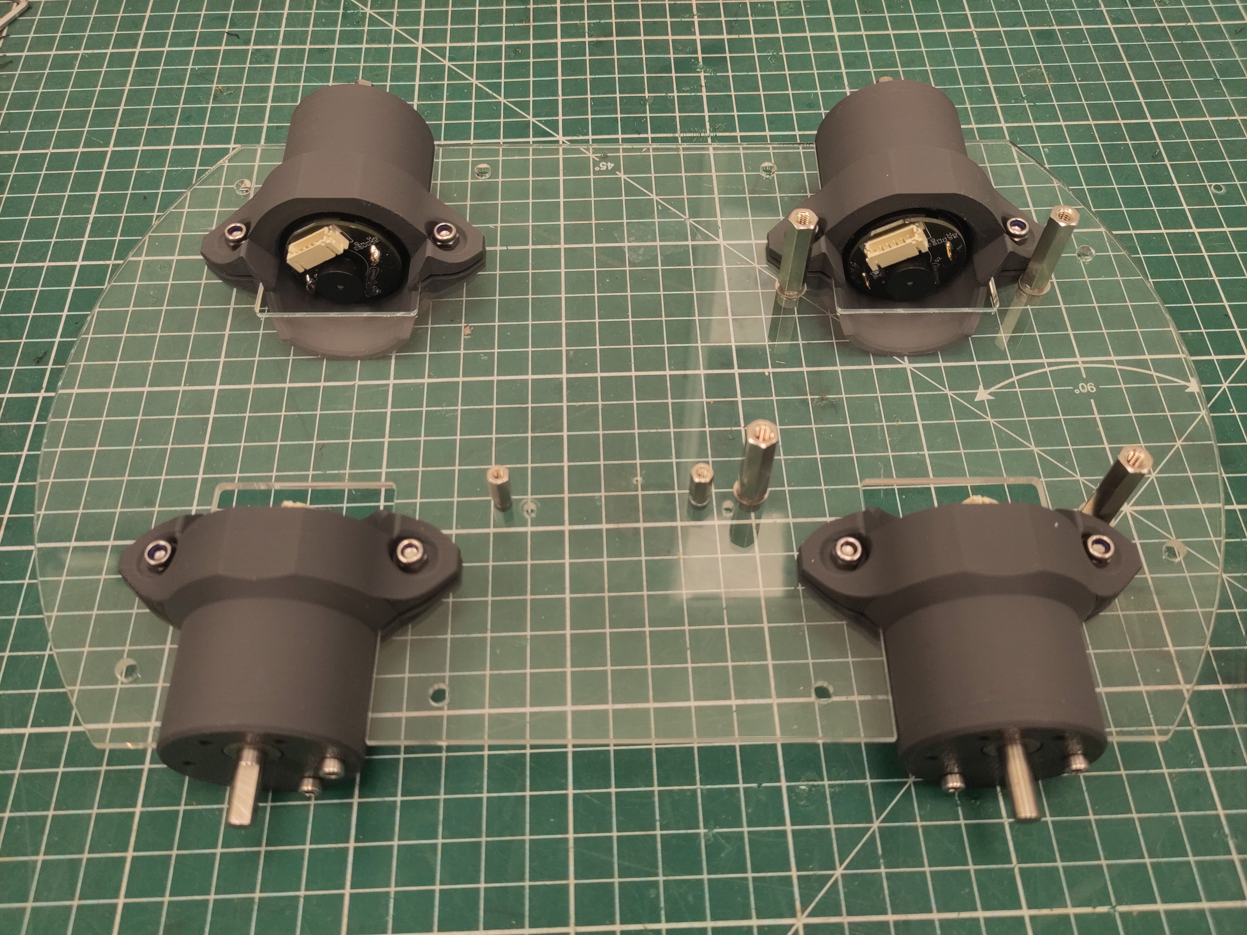
Use the 25mm M4 standoff and M4 x 16 screws (with washer and spring washer).
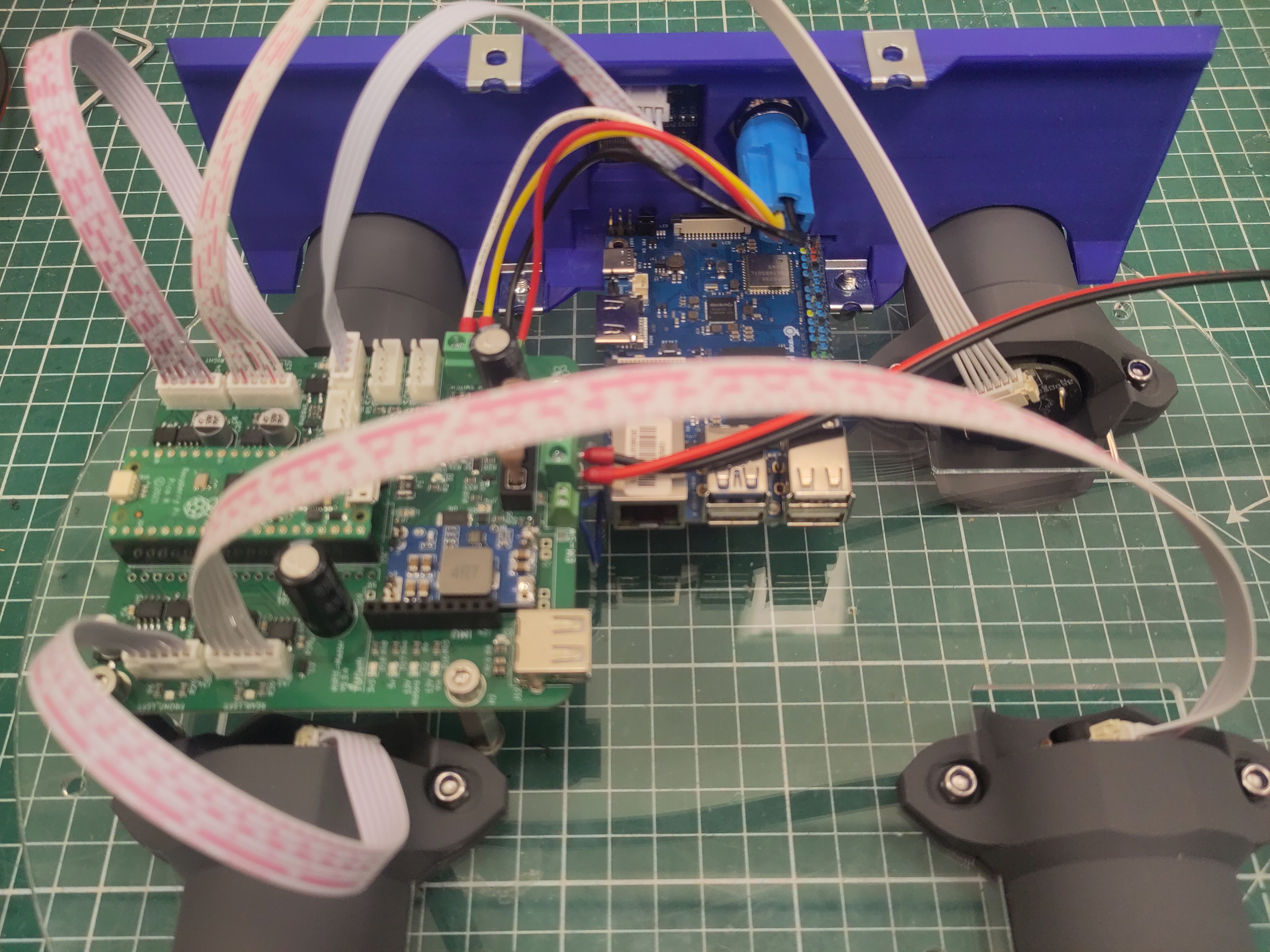
Attach the 30cm JST PH cable to the rear motors.
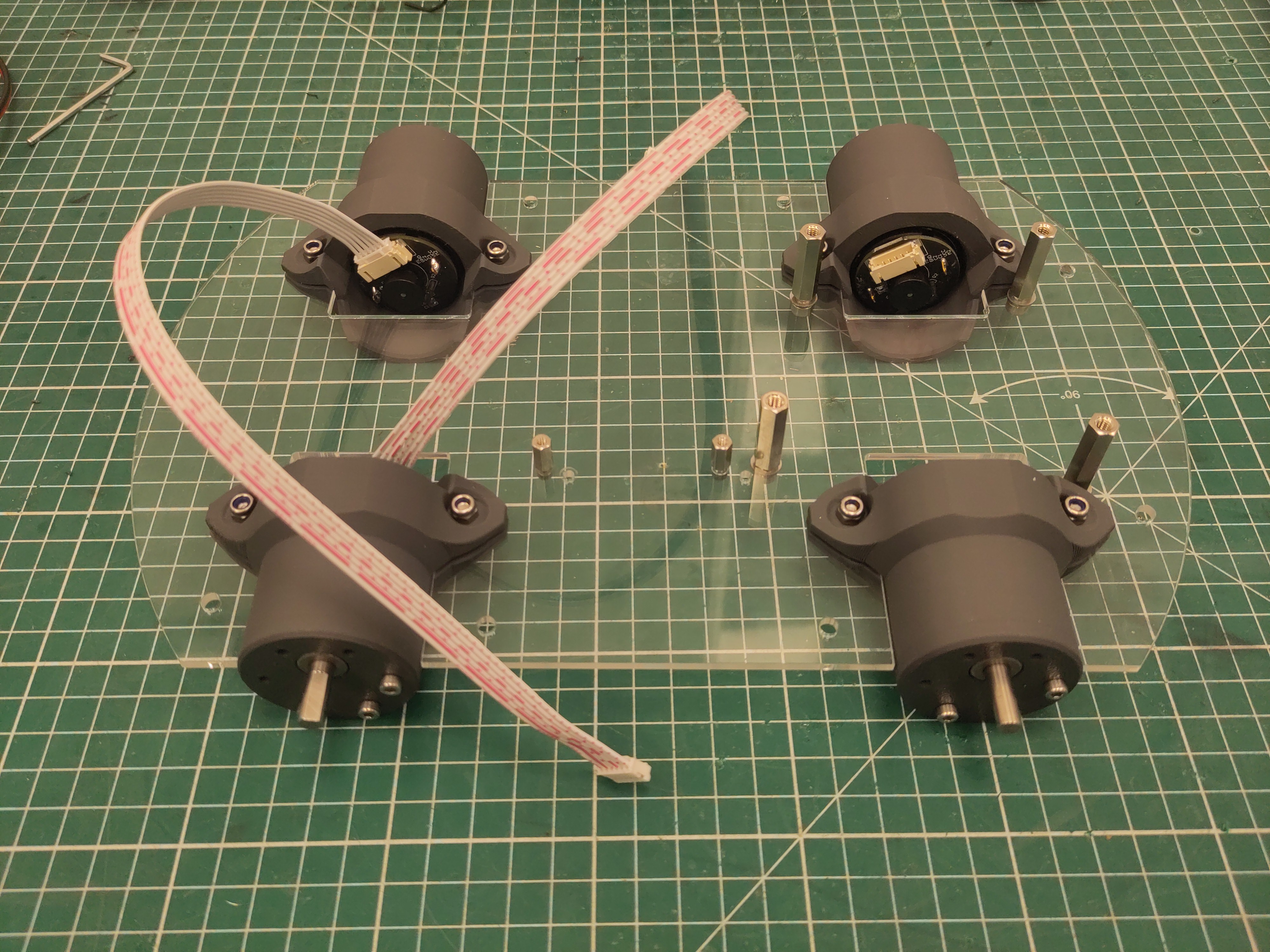
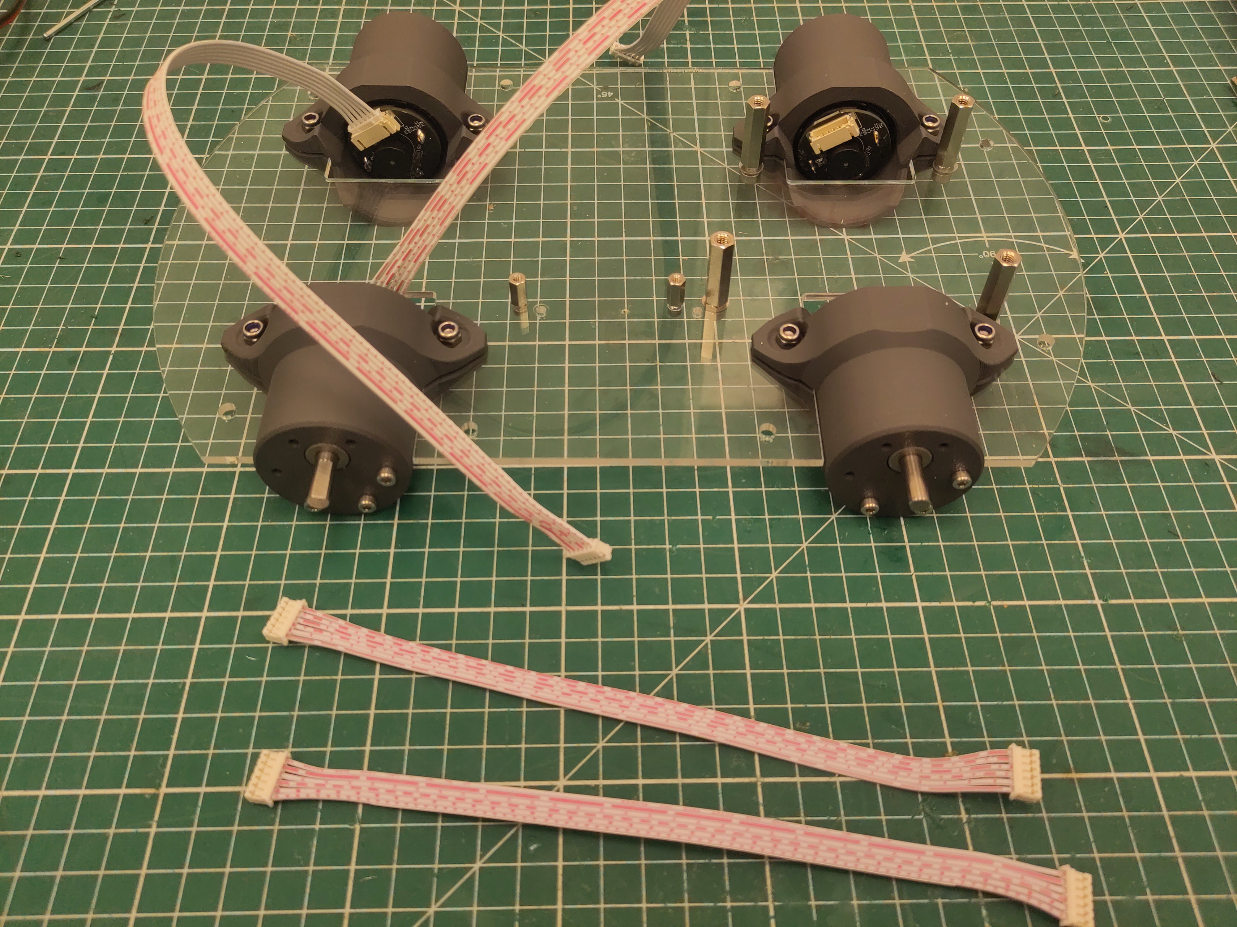
Attach the 20cm JST PH cable to the front motors.
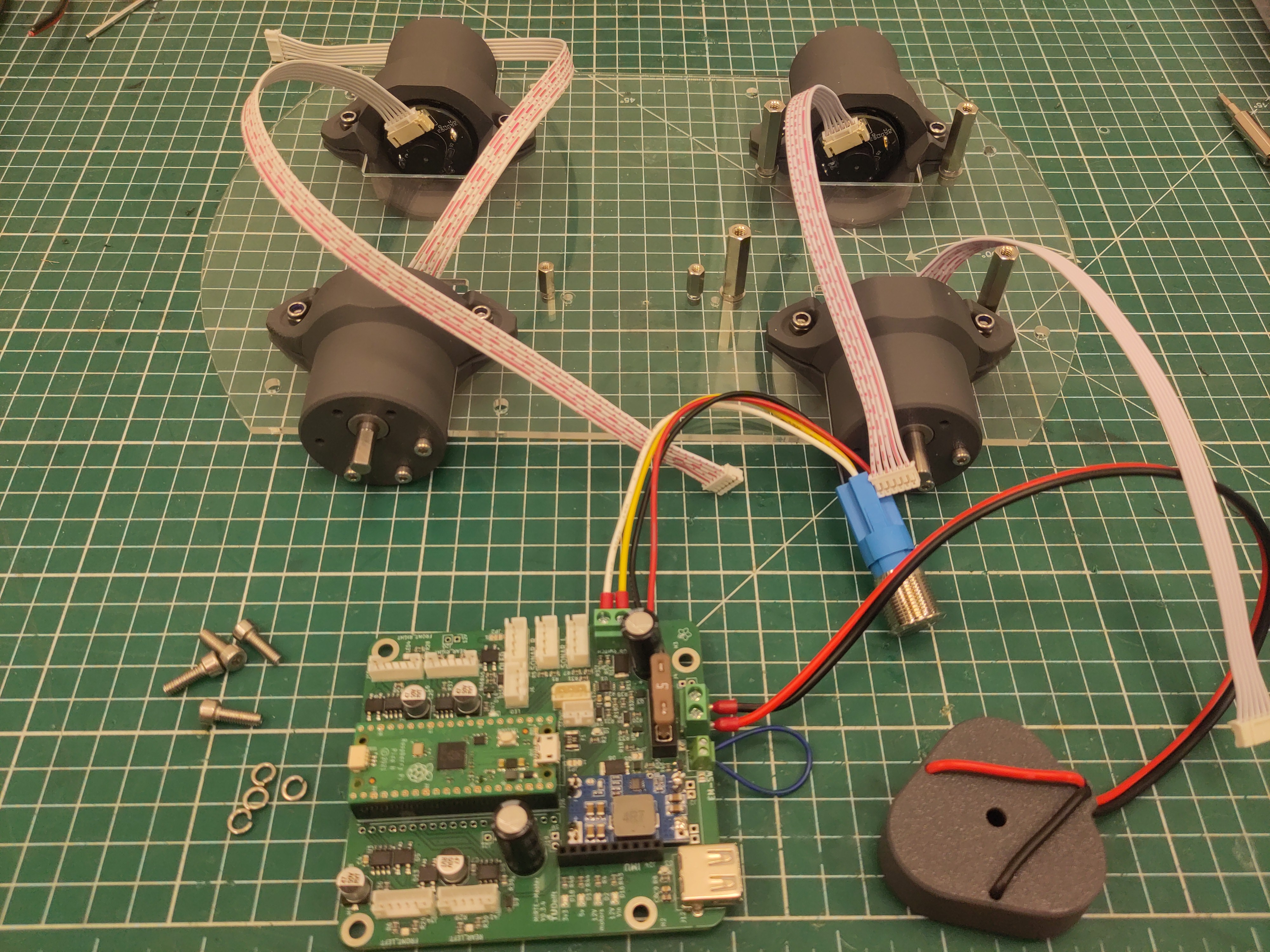
Add the PCB using M4 x 16 screws (with spring washers).
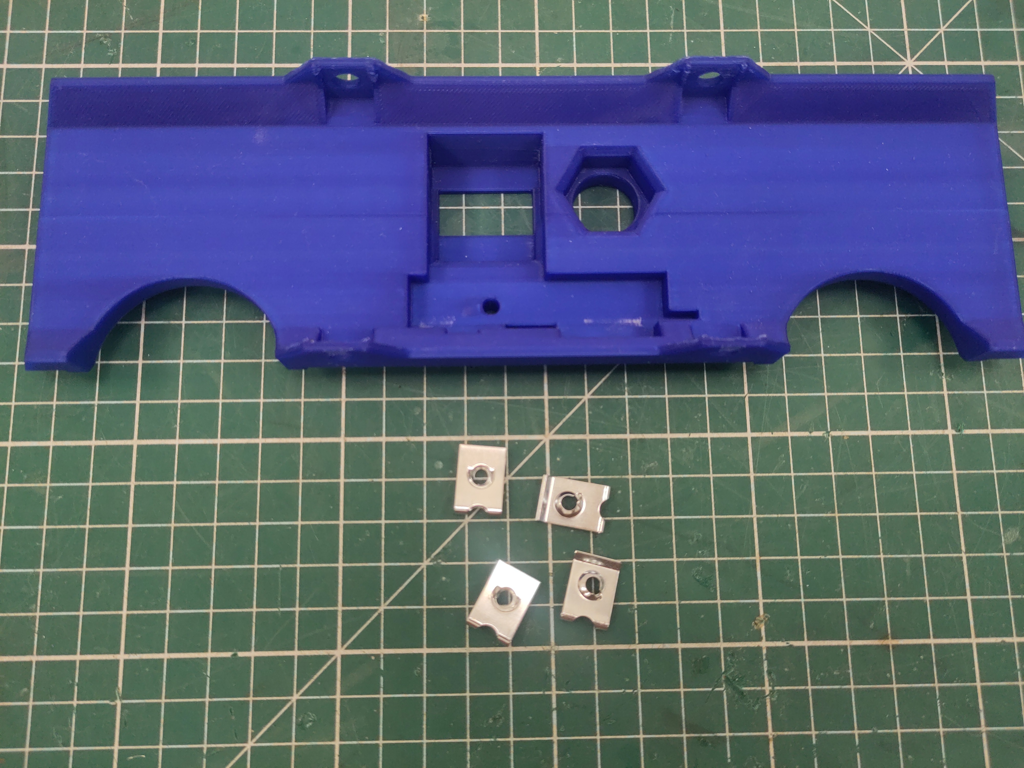
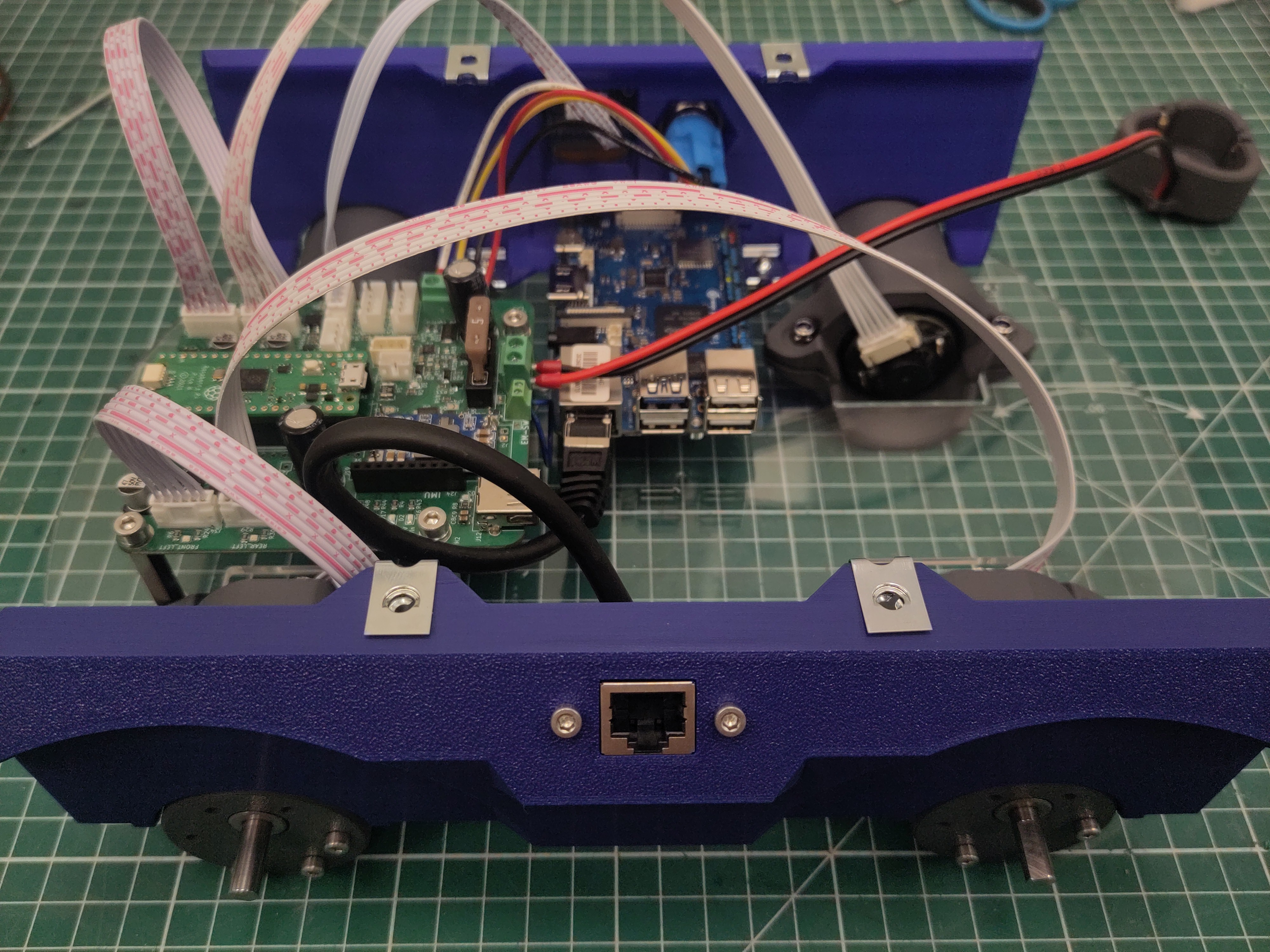
Attach the M4 U-clip captive nut to the side plate.
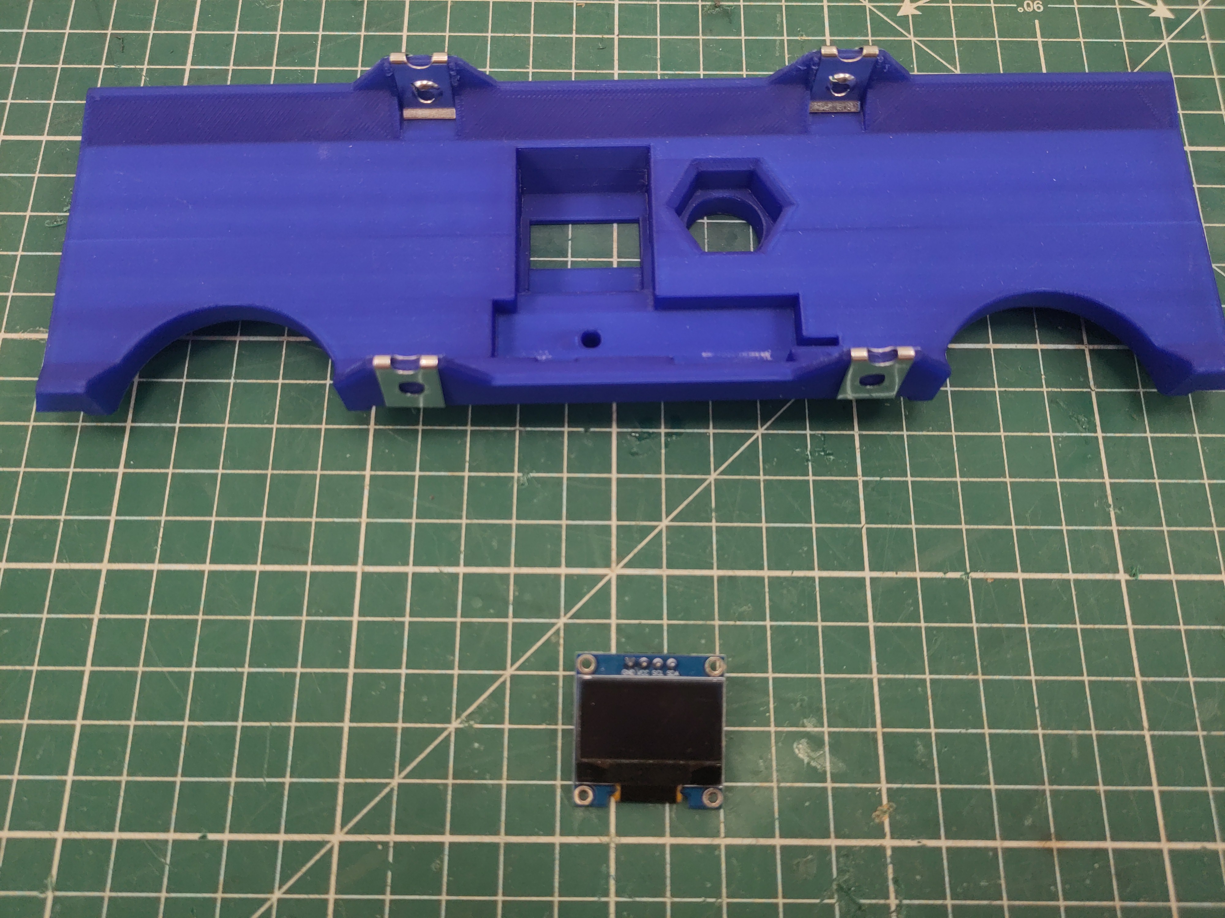
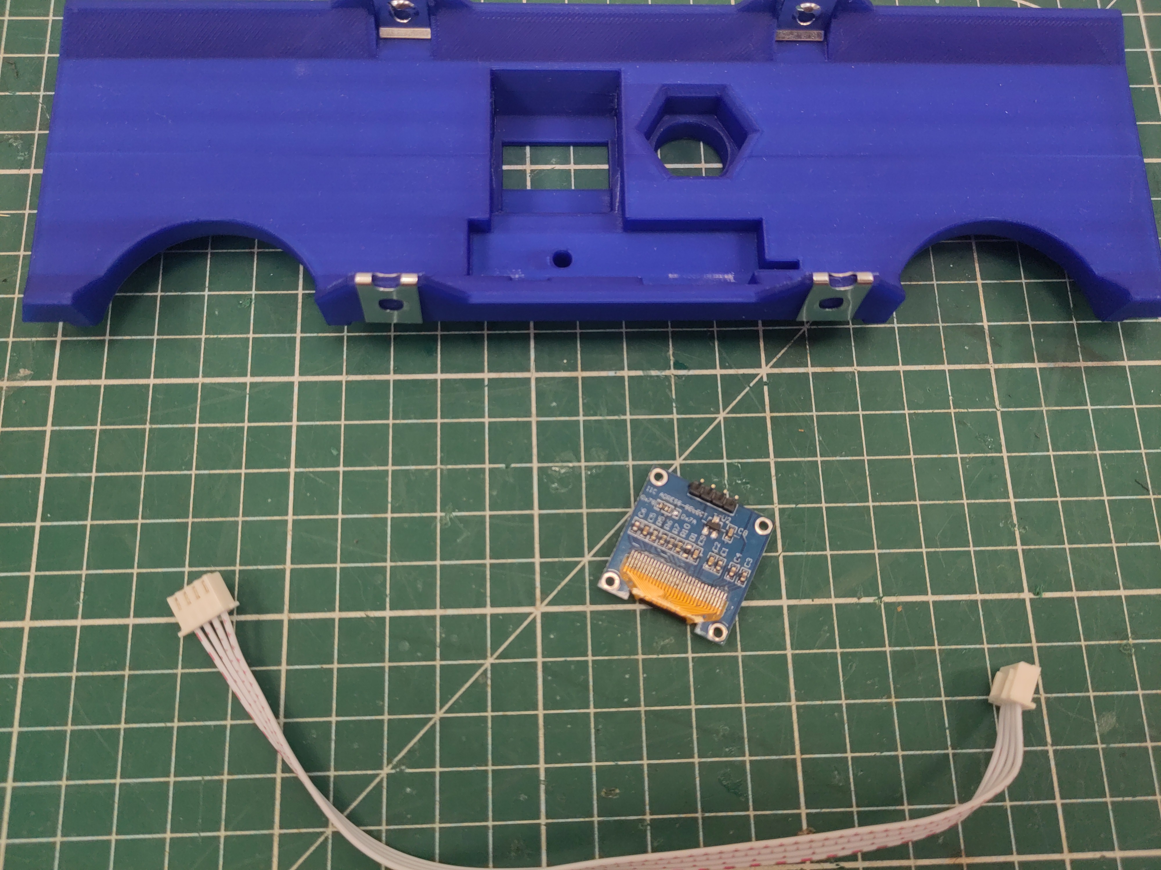
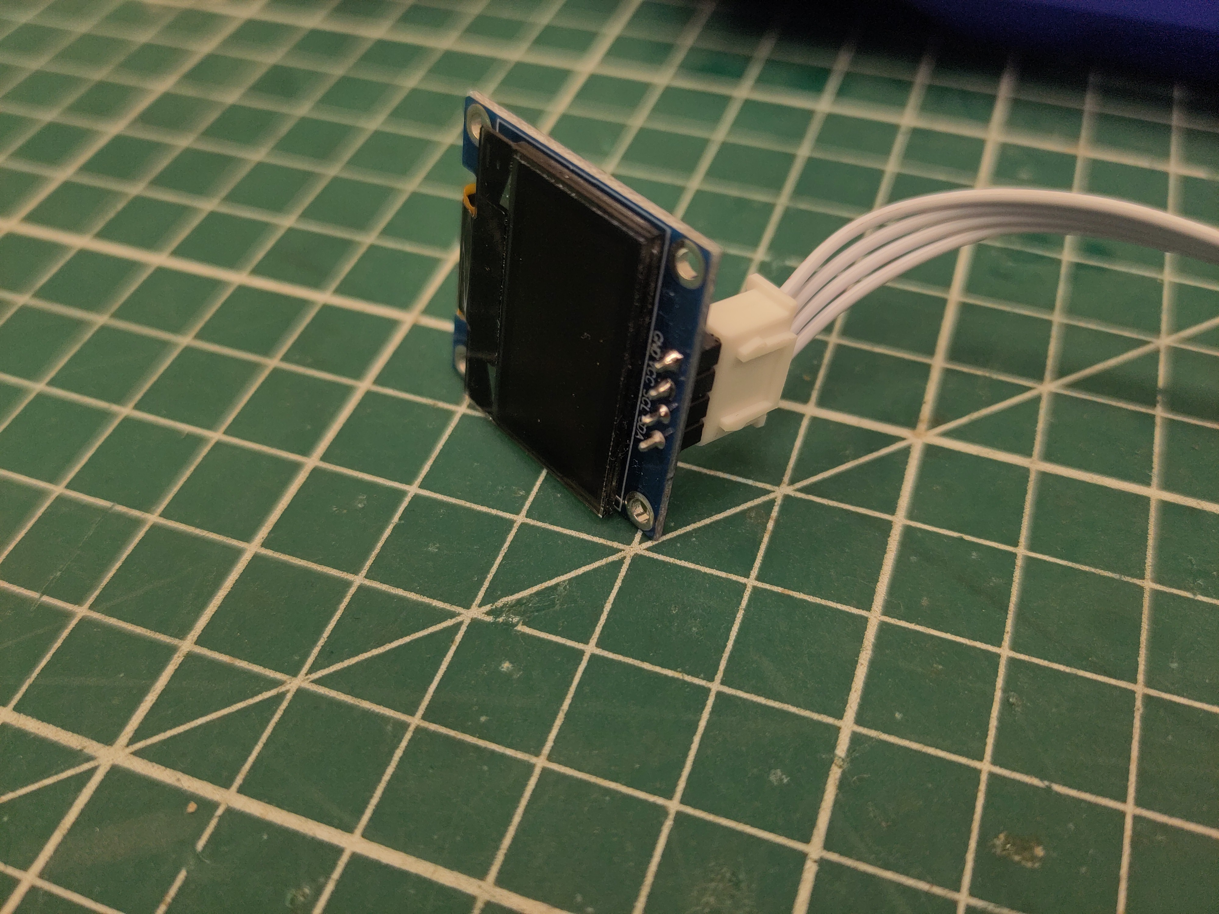
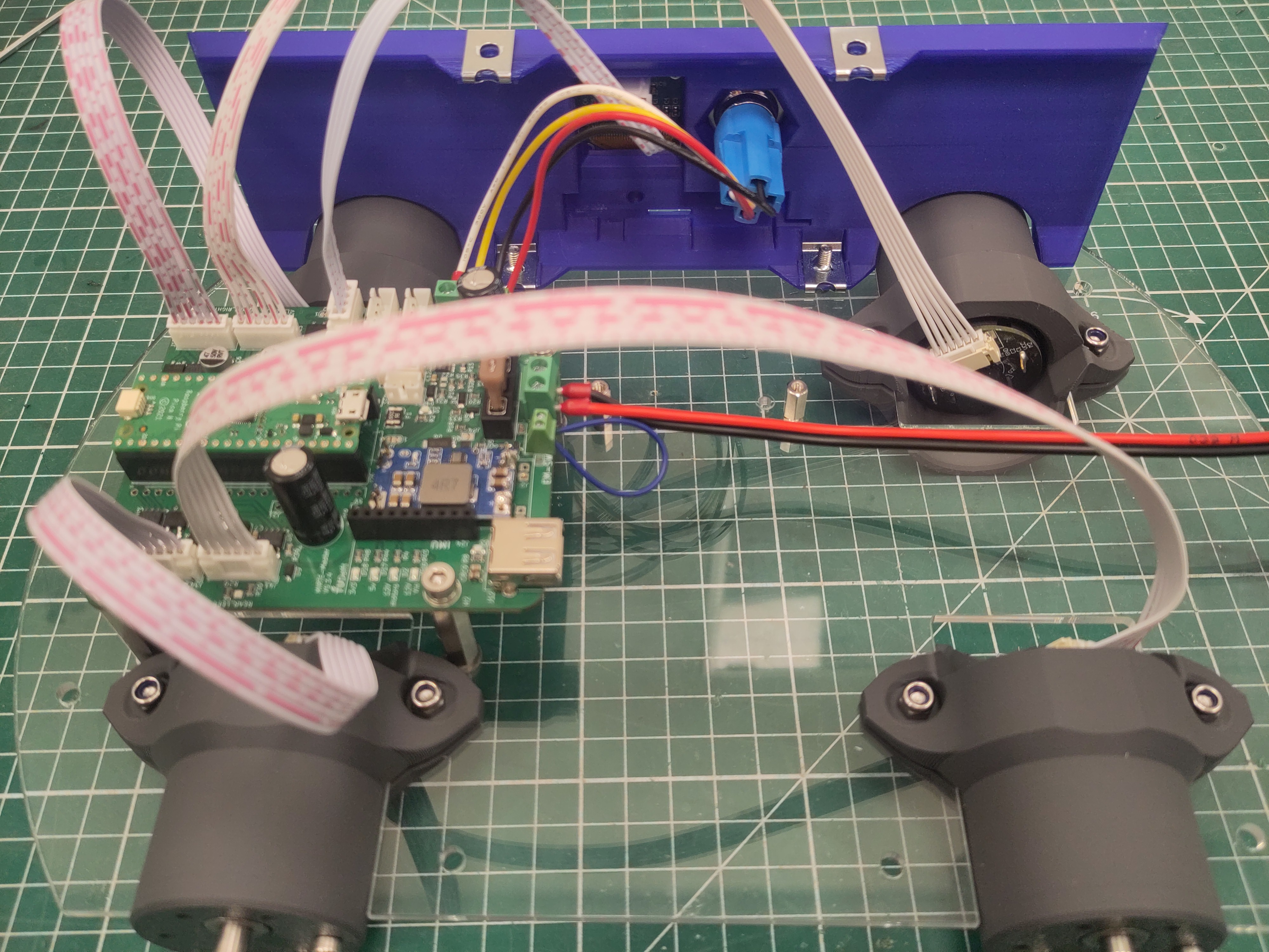
Attach the 20cm JST XH cable to the oled (notice the orientation).
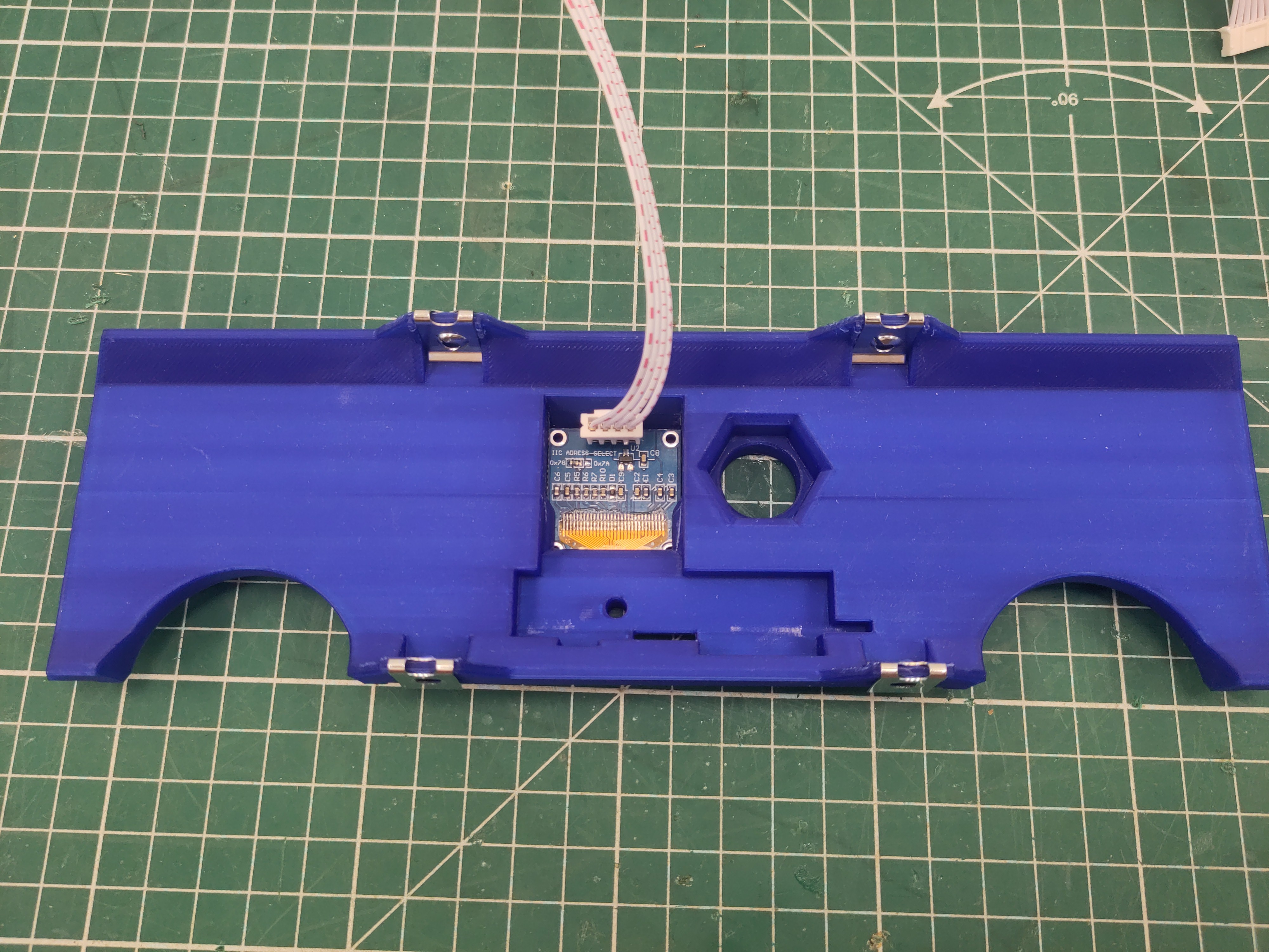
And slide the oled into the side plate.
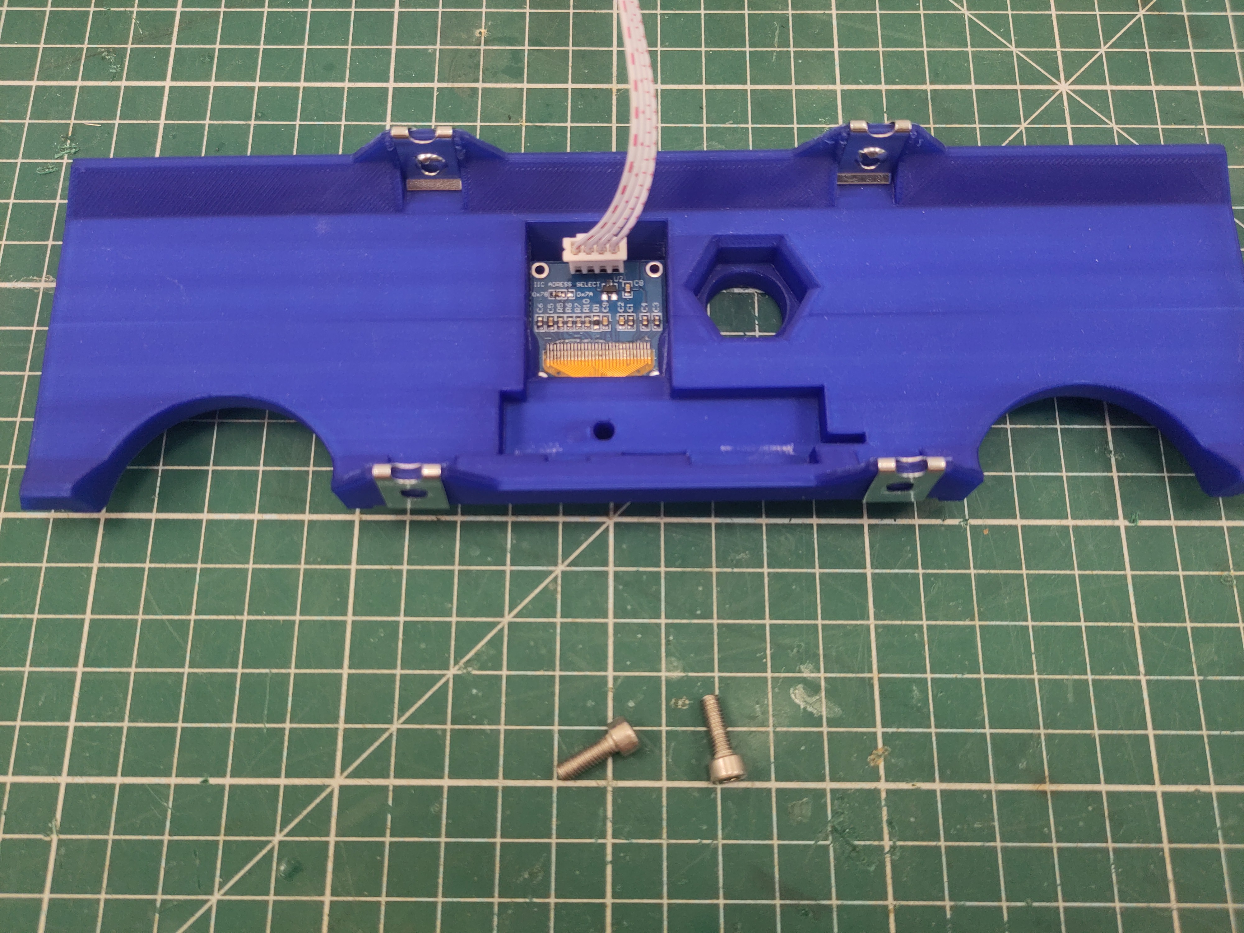
Use M4 x 16 screws to attach the side plate to the bottom plate.
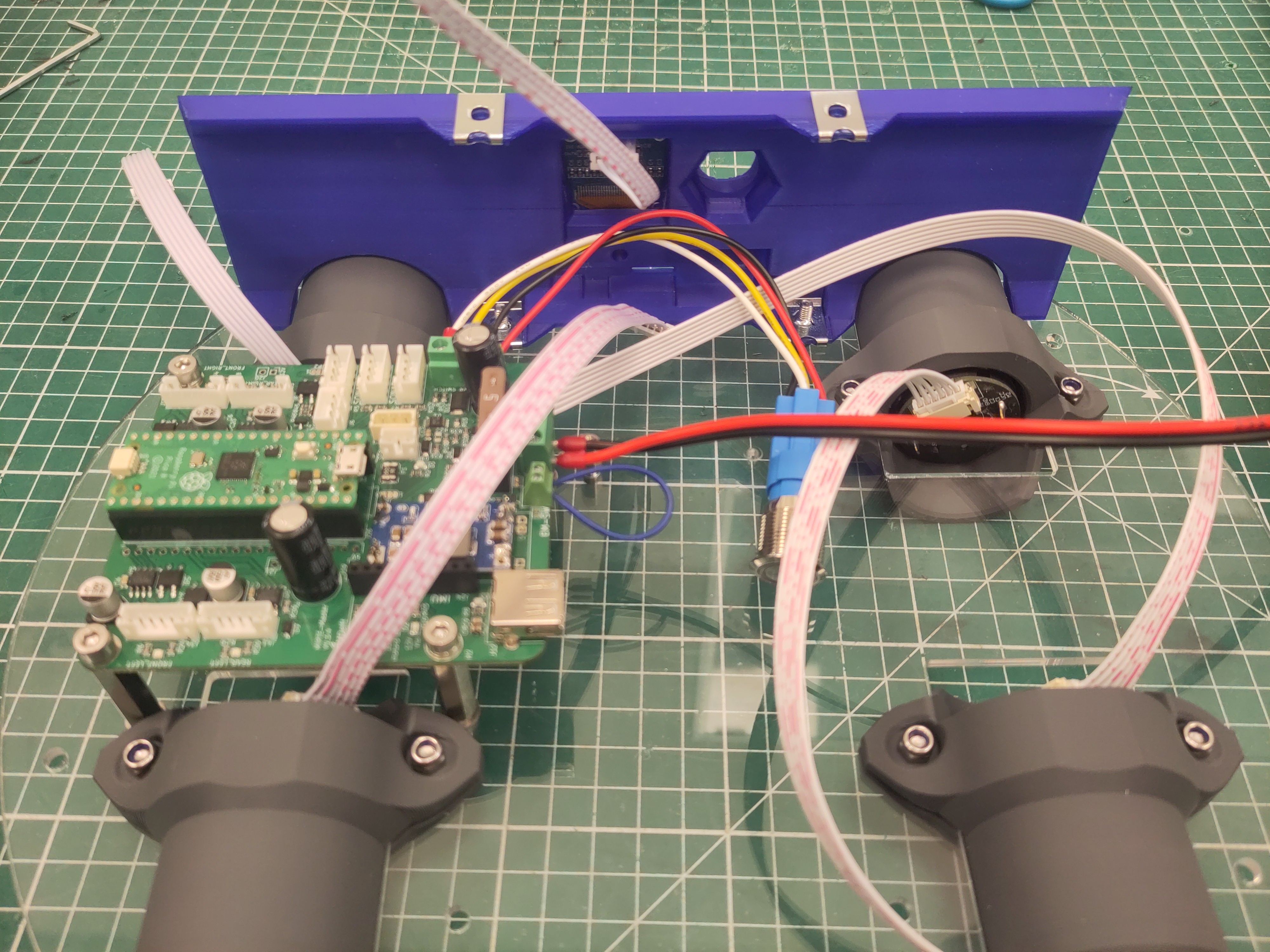
Connect the JST cables of the motors and the oled.
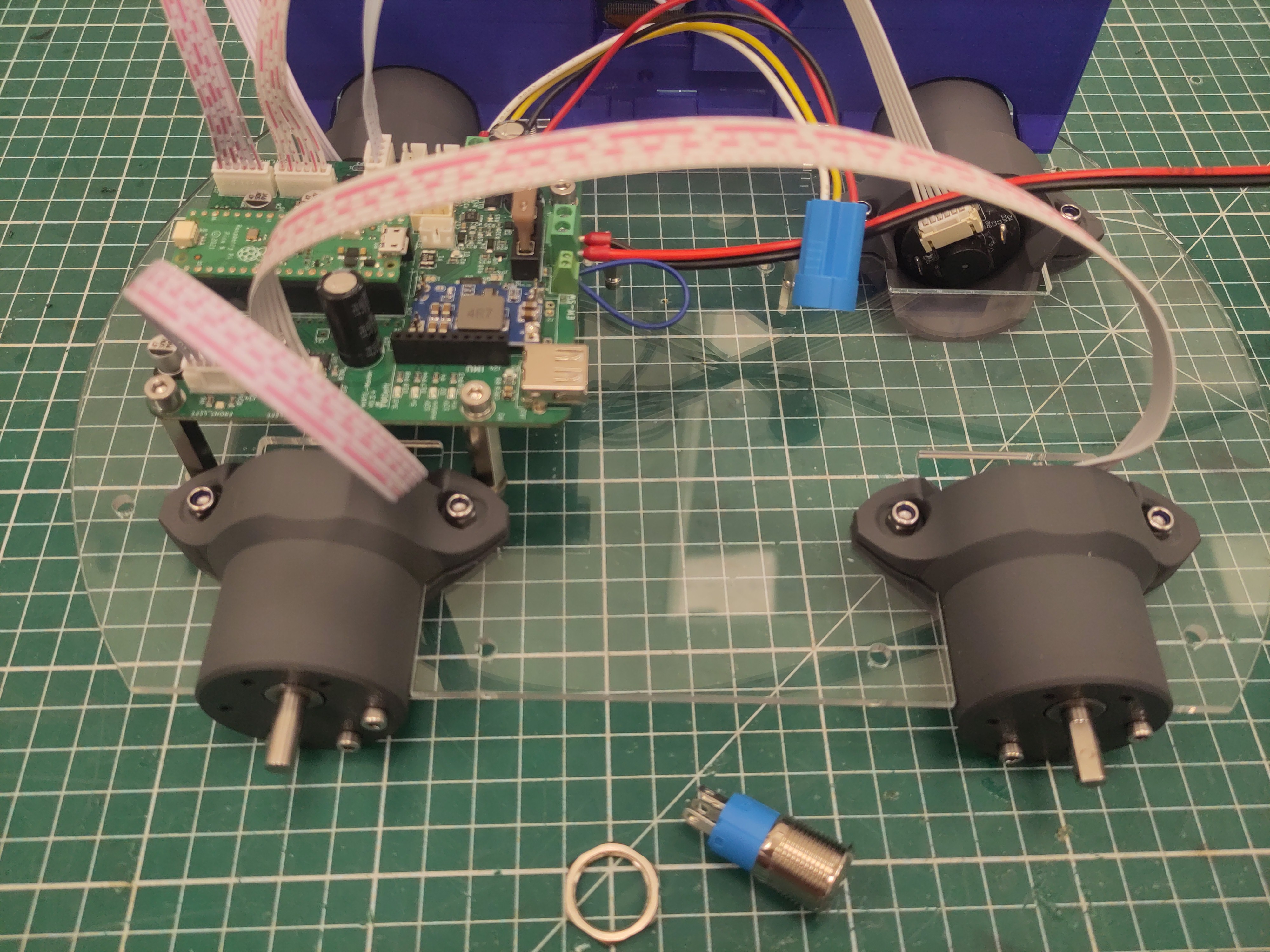
Take the hexagon ring of the switch and attach the button to the side panel.
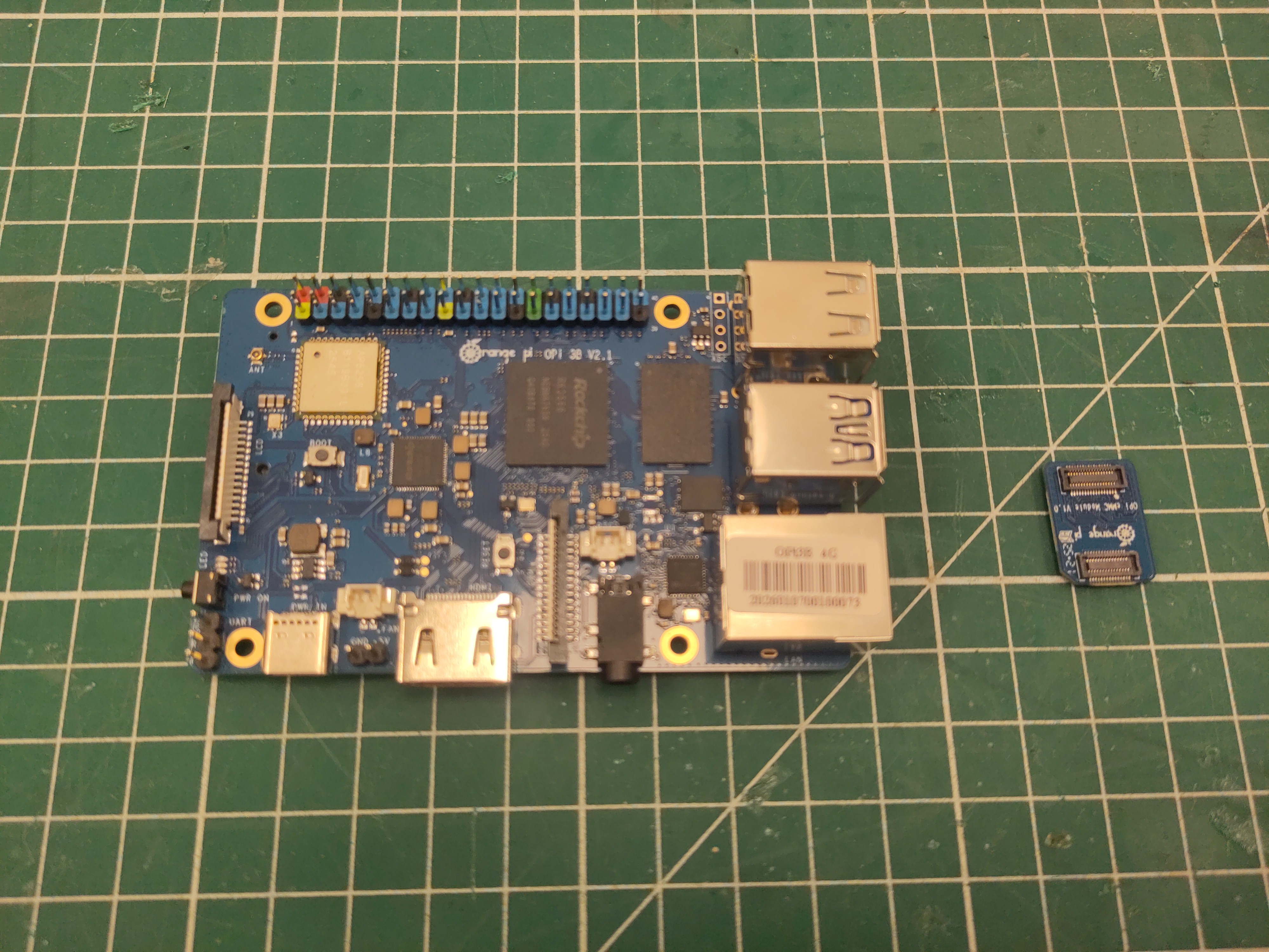
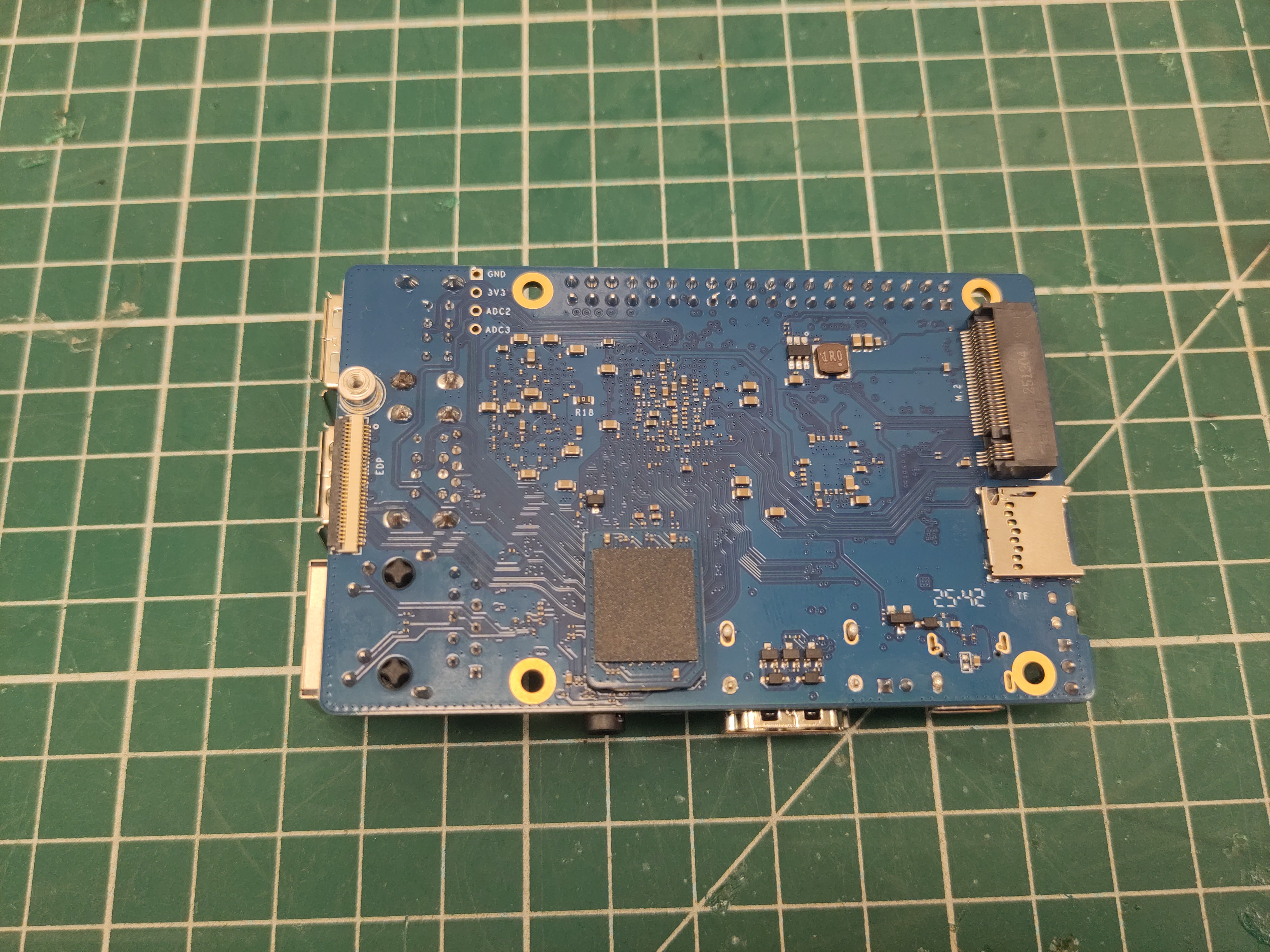
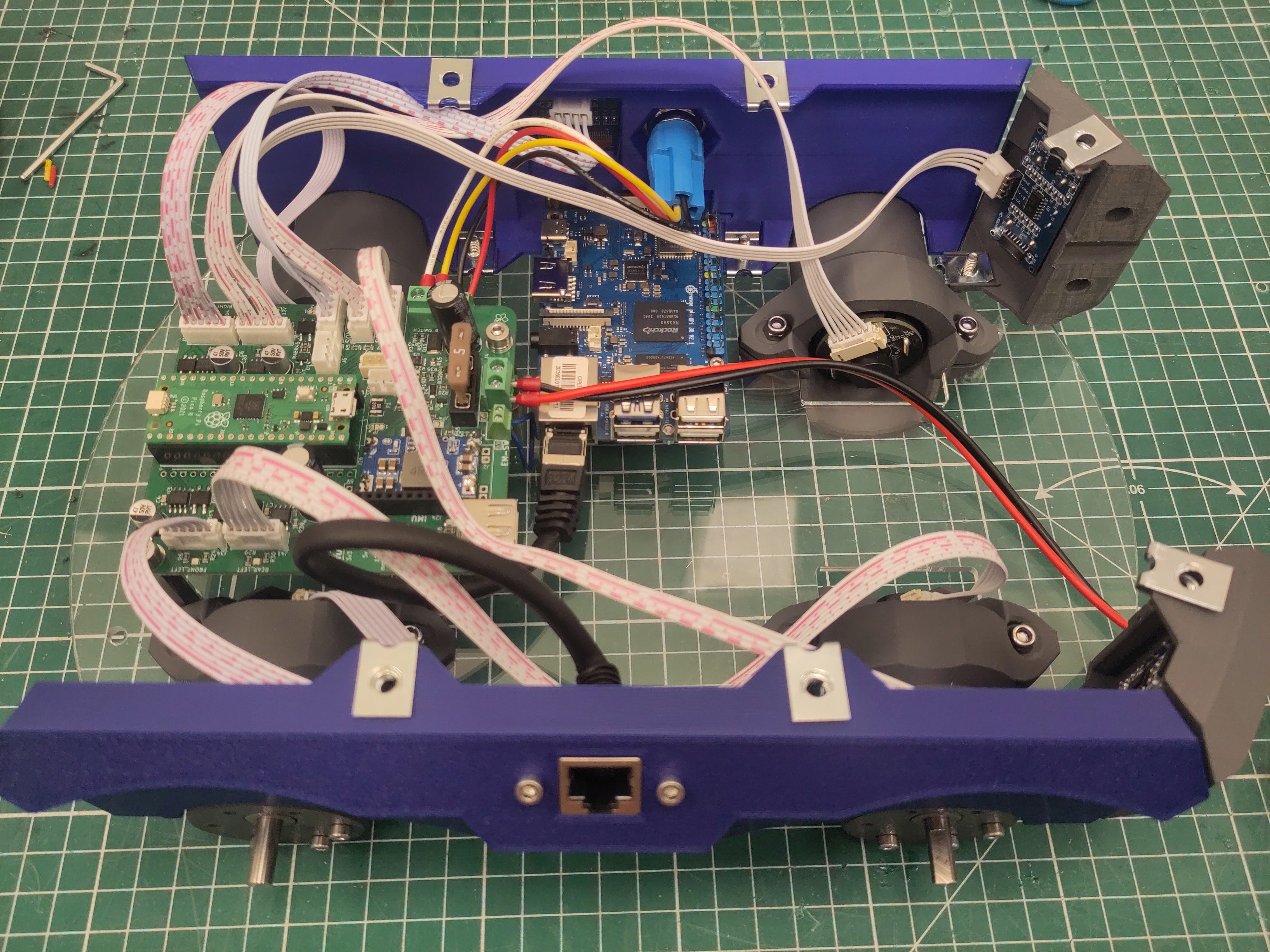
Add the EMMC to the Orange Pi.
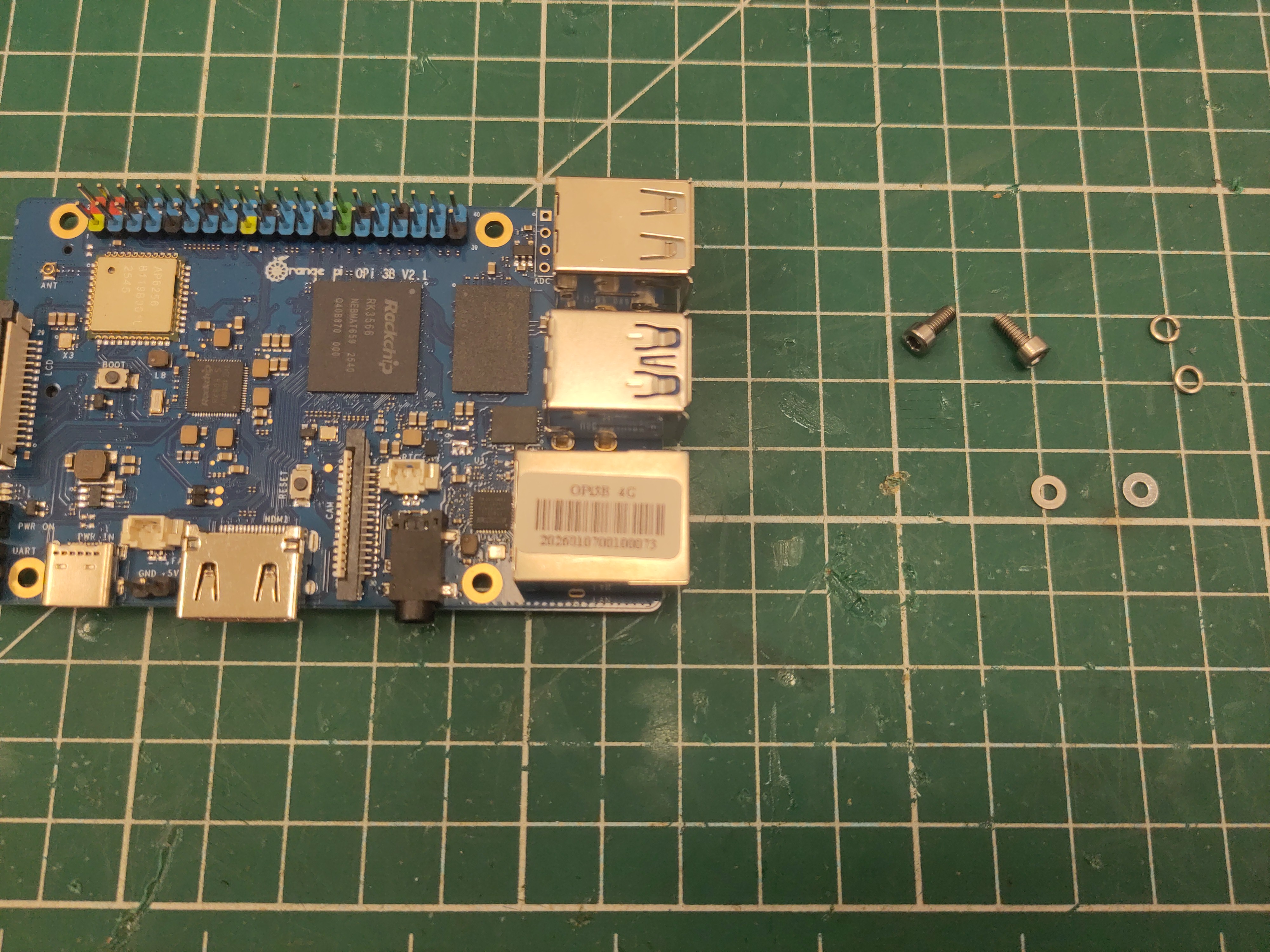
Use M2.5 x 6 screws (with washer and spring washer) to place the Orange Pi.
You might need to loosen the M4 screws of the side panel a bit to correctly place the Orange Pi.
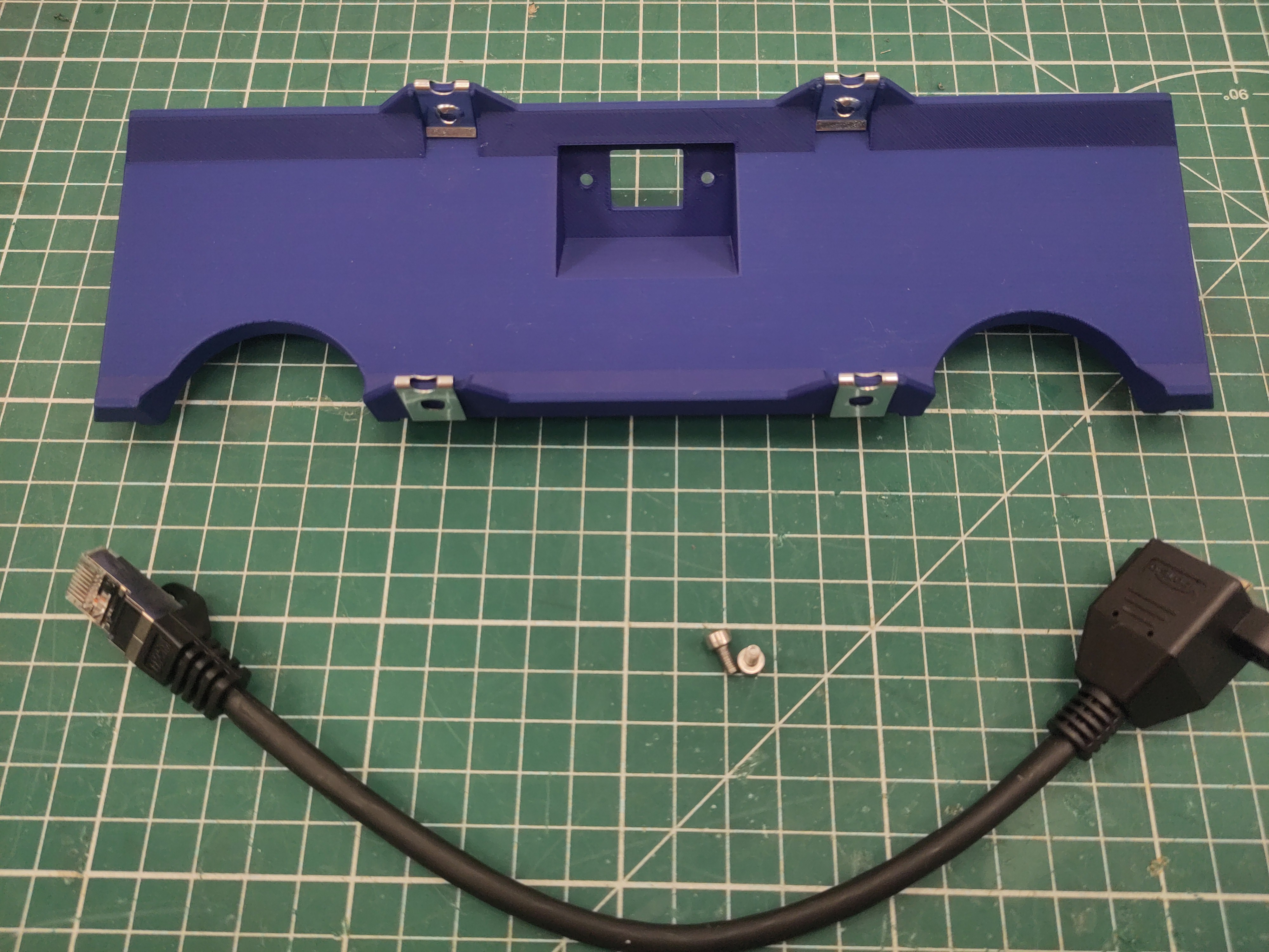
Attach the M4 U-clip captive nut to the side plate.
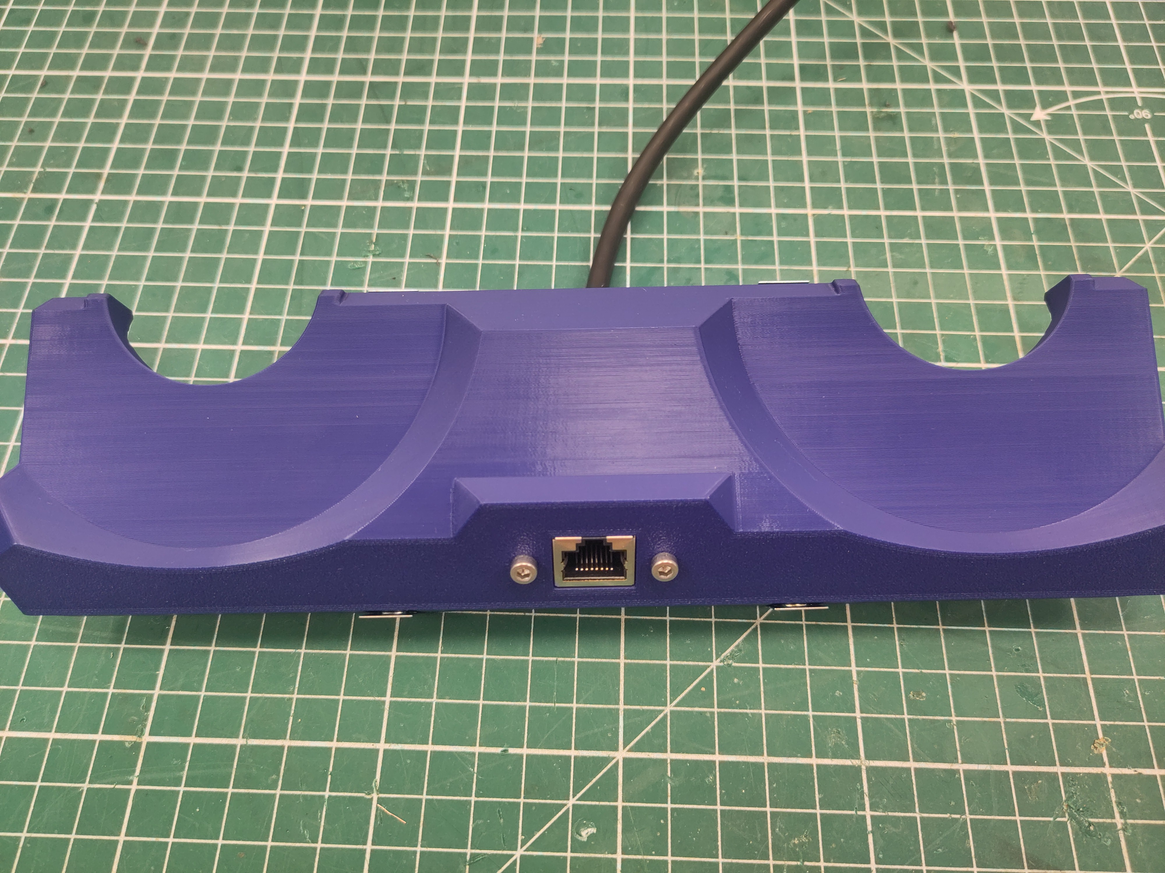
Attach the ethernet extension cable using M3 x 6 screws.
Use M4 x 16 screws to attach the side plate to the bottom plate.
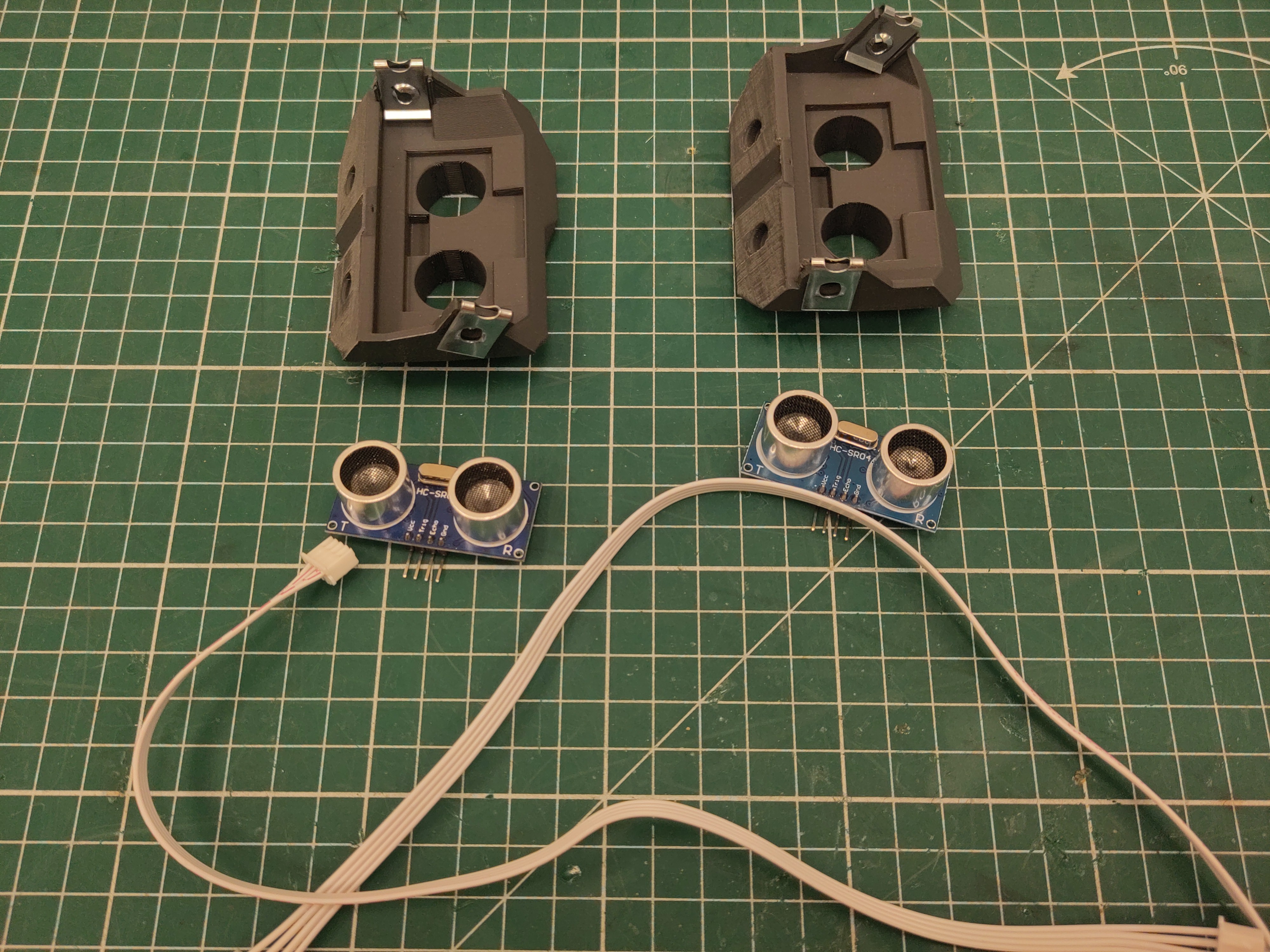
Attach the M4 U-clip captive nut to the ultrasonic modules.
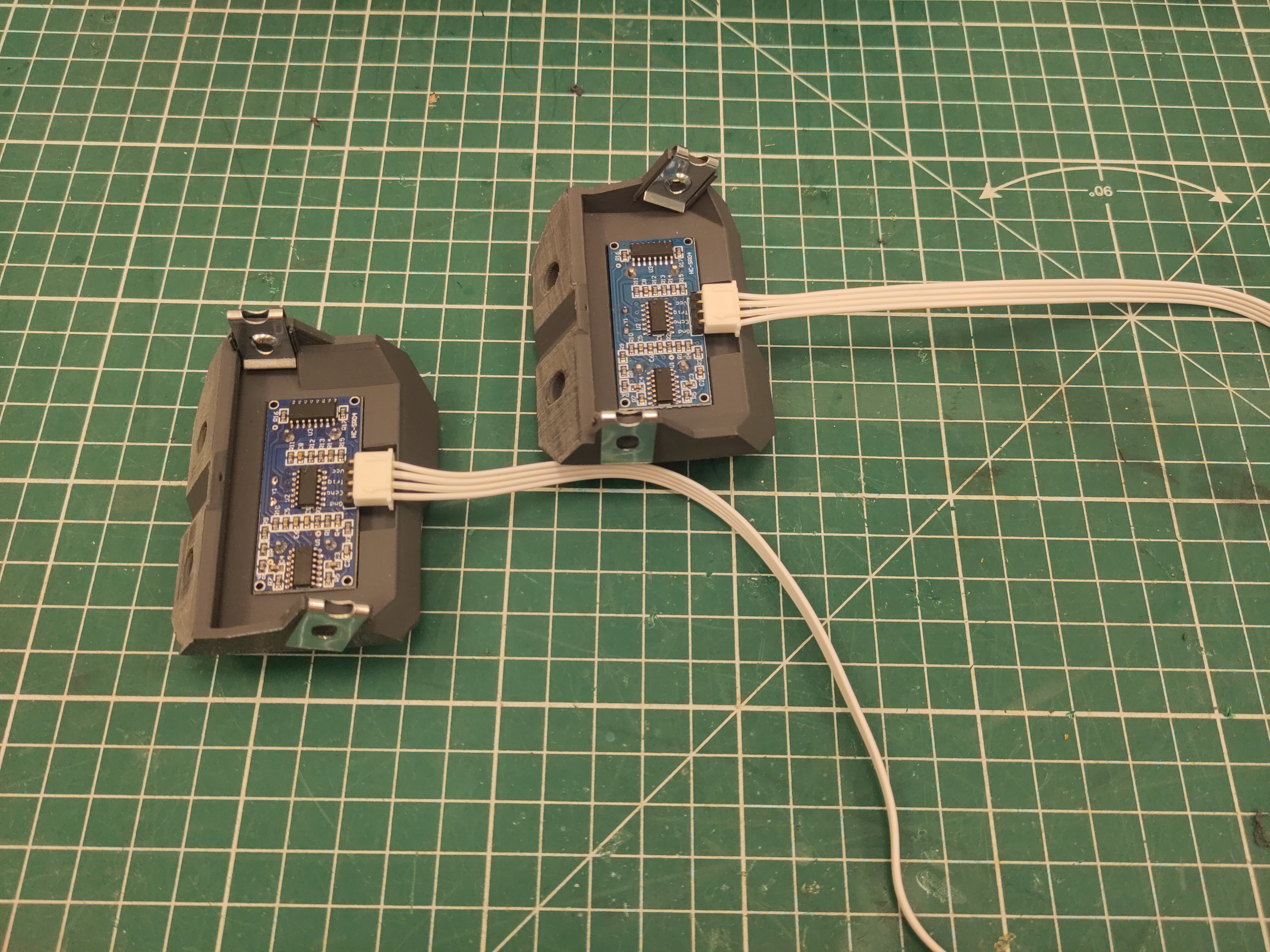
Connect the 30cm JST cables to the sensors (notice the orientation), and place them in the modules.
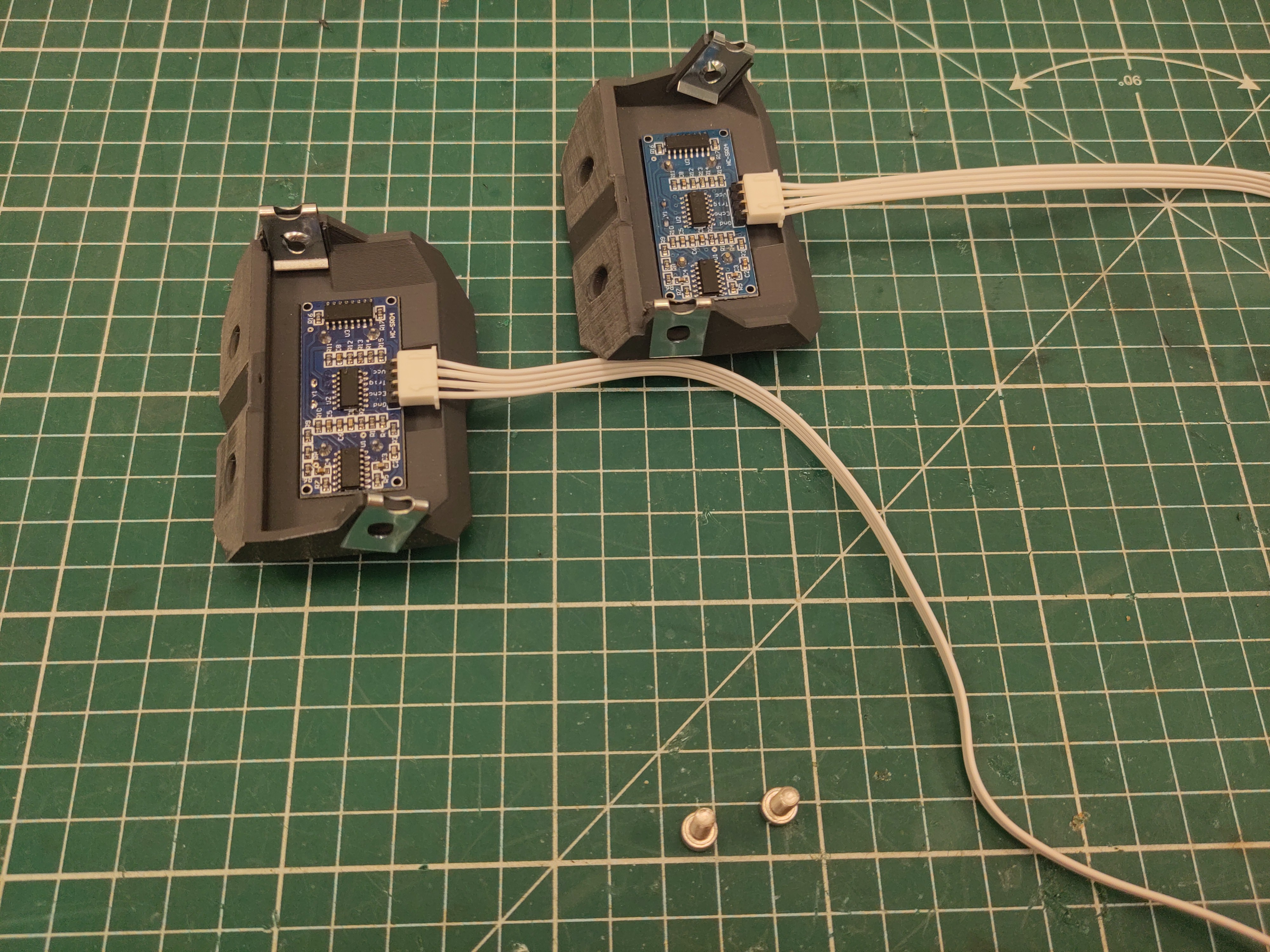
Use M4 x 16 screws to attach the modules to the base plate.
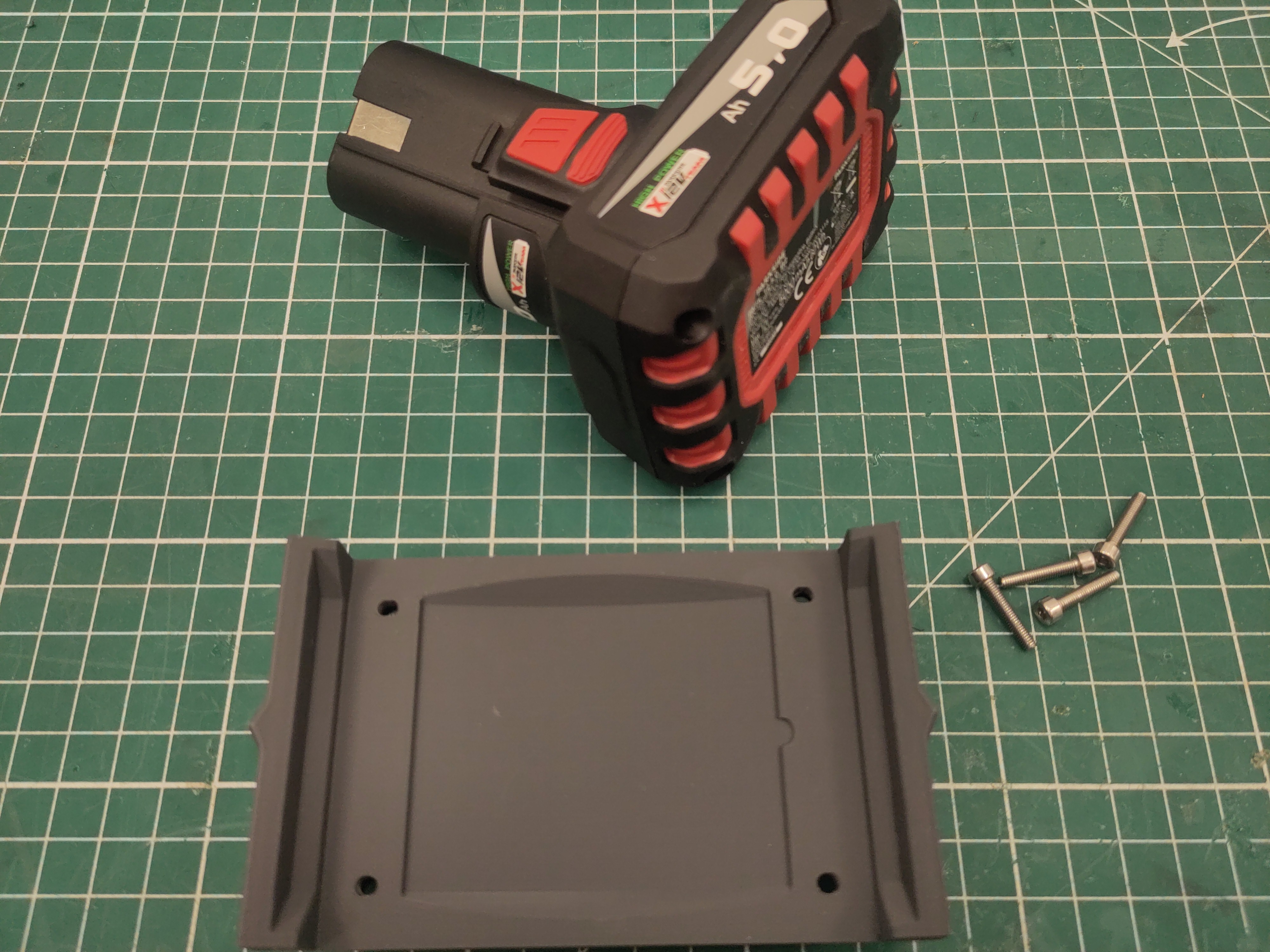
Dismount the screws on the bottom of the battery.
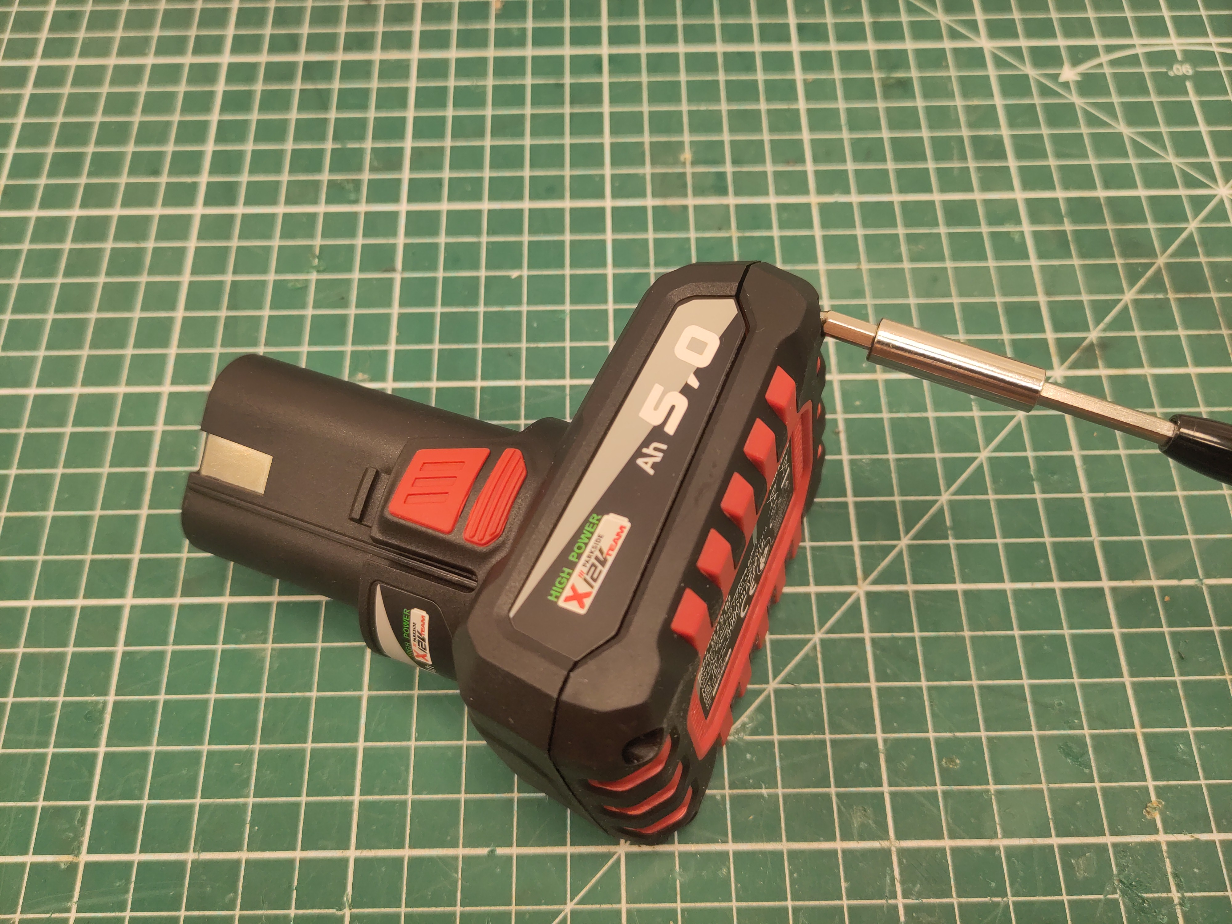
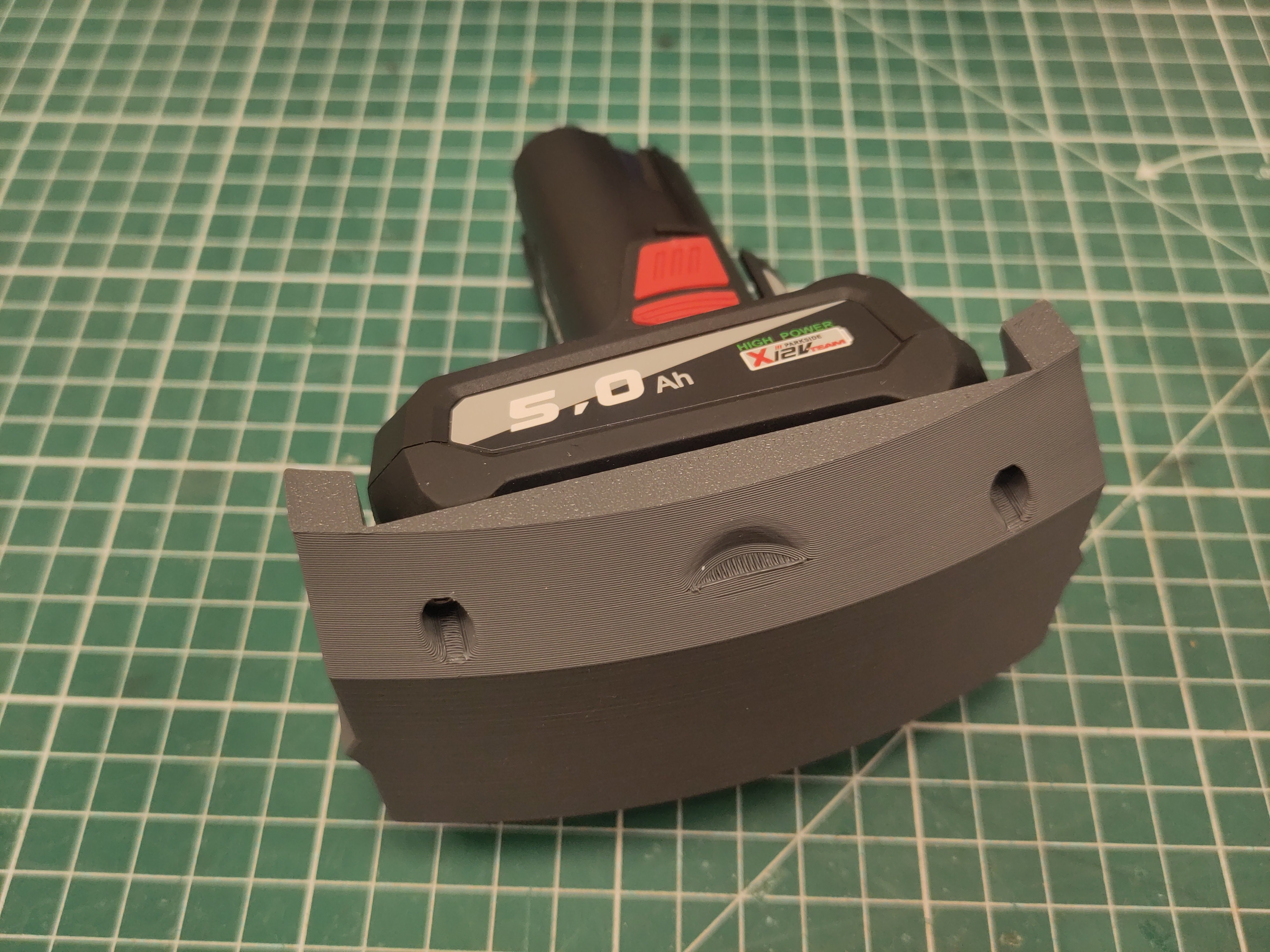
Use M3 x 16 screws to attach the battery module to the battery.
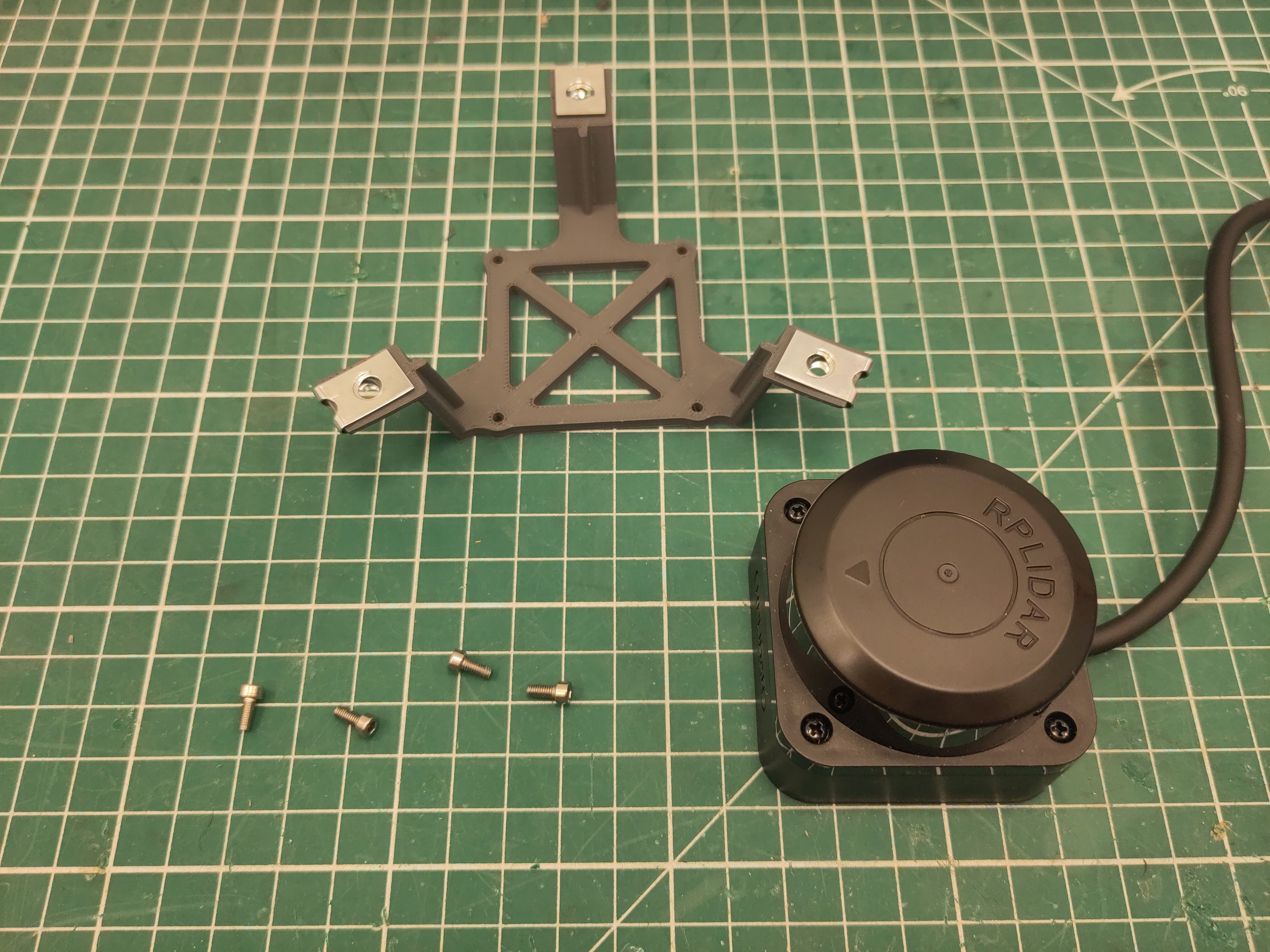
Attach the M4 U-clip captive nut to the ultrasonic modules.
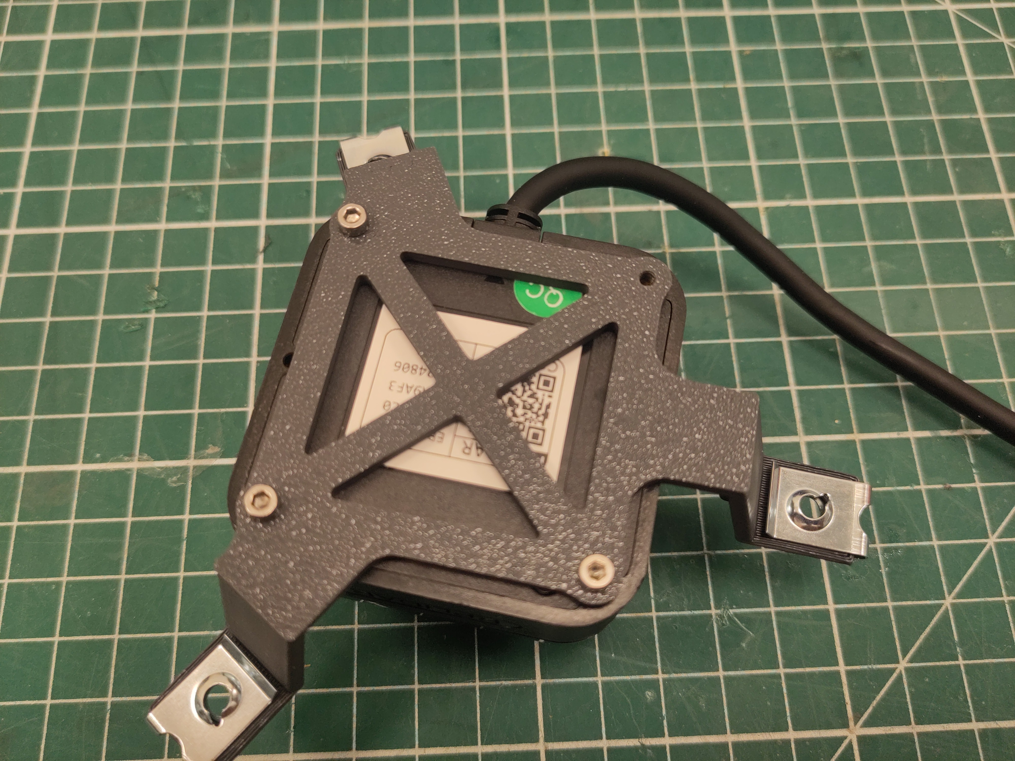
Use 3 of the M2.5 x 6 screws to attacht the lidar.
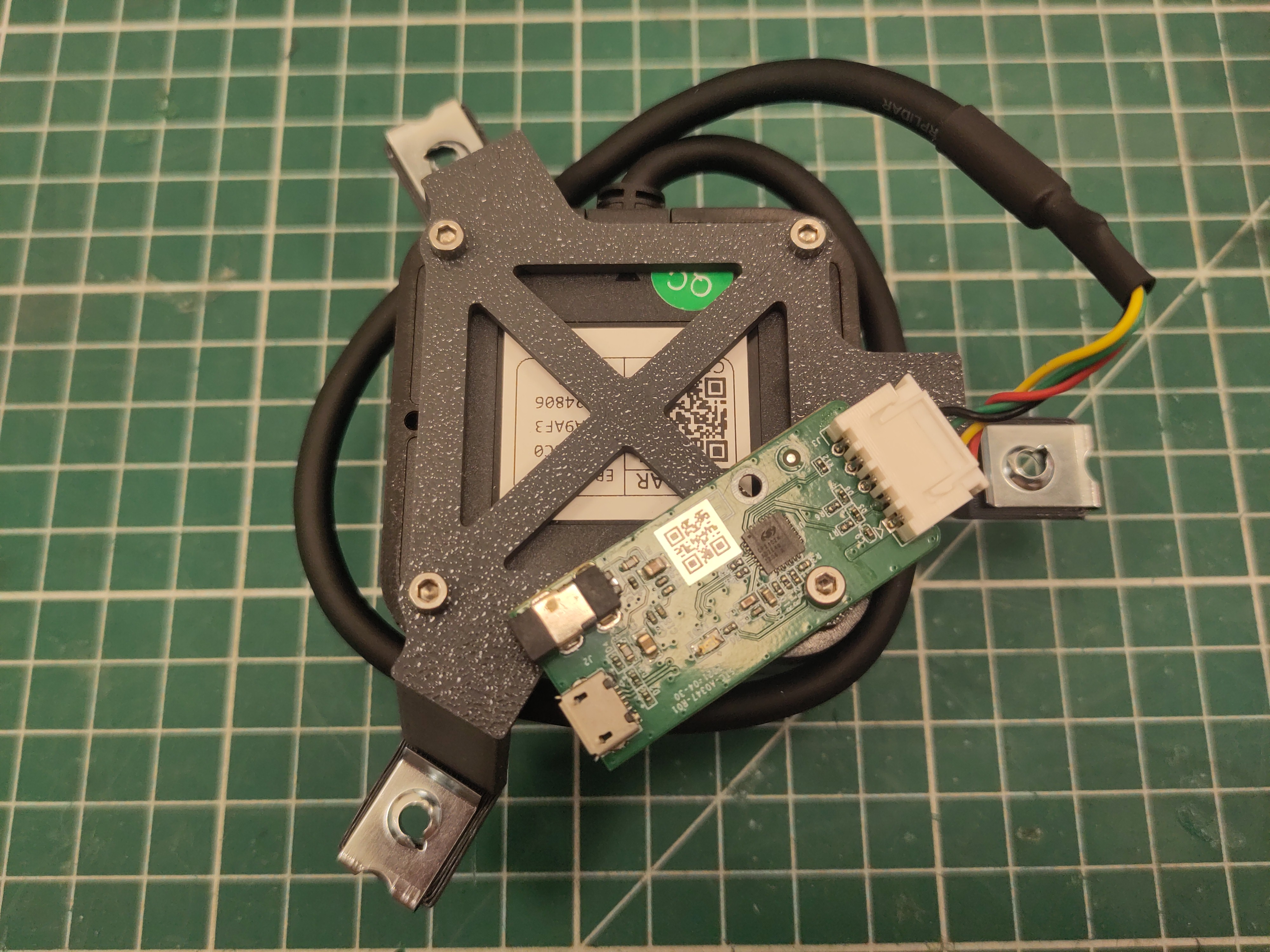
Use the last M2.5 x 6 screws to attacht uart-board to the lidar.